14
DataXport is finished with copying data from the built-in
data table in DynaFLO
’s controller.
If the built-in data table in DynaFLO
’s controller requires
more memory than what is available in the controller <On
Board Memory Status> will change from <OK> to <On
Board Memory Full>.
5.2.3.3
– DataXport
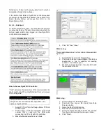
To build a DataXport project, you first define the project’s
modules listed below. These modules determine when the
data is logged, which data is logged, and how DynaFLO
’s
controller can be accessed.
How to Access DynaFLO
’s Controller:
“Ports” determine the parameters of the communication link
that is used by the PC running DataXport In order to access
PLC and log data.
NOTE
The controller name must be identical to the name
assigned in the controller’s ladder application. This
name is: DynaFLO PLC
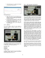
1. Select PC Ports from the Design Menu; PC Ports
window opens.
2. Double-click a line that corresponds to the COM
number that is used with the USB cable
connecting the PC to DynaFLO
’s controller.
3. Make the desired selections as follows:
4.
Click “OK” then “Close”.
When to Log:
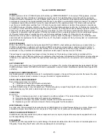
The schedule determines the time intervals between data
log actions.
1. Select Schedules from the Design Menu.
2. Click Add to create a new schedule, click Edit or
double-click a line to redefine an existing
schedule, the schedule open.
3. Make the appropriate entries, then click OK to add
the schedule to the list.
What to log:
1. Select Tables from the Design Menu.
2. Click Add, then click on the Import Data Table
Structure button.
3. Name the Data Table Structure.
4. Read the structure from the PLC.
5. Select the Data Table Structure that was just read
from the controller under the name you chose.
6.
Click “Close”.
Содержание DynaFLO DOWB-S1 Series
Страница 2: ......
Страница 25: ...22 Appendix B Electrical Schematics DynaFLO ...
Страница 27: ...24 ...


