9
WARNING!
MODBUS MASTER SHALL NOT WRITE INTO ANY REGISTER THAT IS NOT INCLUDED IN THE ABOVE TABLE!
* Note: DynaFLO
’s PLC’s Registers are 0-based thereby for e.g. MI0 = Modbus 40001 (Unless the Modbus software also uses
its own offset in which case the specific software has to be consulted.)
** Note: These commands are for reference only as each Modbus software has a different interface with different options and
ways of converting commands.
5.2
– Screen Navigation
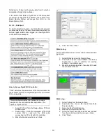
The chart below shows the controller’s menu structure.
The start-up screen lists three options, <Control>, <Setup>
and <Alarm>. Each option is explained in the next section. On
the top right there is a display that indicates that status of
alarms.
The controller uses a two-tiered password protection scheme.
The low level password is needed to access the Setup menu.
The higher level password is needed for configuring the P, I
and D parameters as these parameters are no recommended
to be changed.
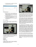
Modbus Map
Parameter
Register*
Traditional
Modbus
Reference**
Read/Write
Notes
16 Bit Registers
40010
R
DHW Out Temp. Read
MI 9
Set Point Read
MI 97
40005
R
Actuator Position (%) Read
MI 95
40096
R
Set point Write
MI 87
60088
W
Only Possible when the
control is set to Remote
Setpoint
Actuator Position Write (%)
MI 96
60097
W
Only Possible when the
control is set to Remote
Direct
Memory Bits
10024
R
Low Temp. Alarm Active Notifier
MB 23
High Temp. Alarm Active Notifier
MB 26
10027
R
RTD1 Alarm Active Notifier
MB 29
10029
R
AI1 Failure Alarm Notifier
MB 35
10036
R
Low Battery Alarm Notifier
MB 38
10039
R
One or more Alarms is Active
MB 20
10021
R
Clear All Pending Alarms and Rescan
MB 19
50020
W
If all conditions for all
alarms have been satisfied,
this can ACK any pending
alarm that is not active
anymore. However, this
also clears such alarms
from alarm history.
Содержание DynaFLO DOWB-S1 Series
Страница 2: ......
Страница 25: ...22 Appendix B Electrical Schematics DynaFLO ...
Страница 27: ...24 ...


