background image

Section 3.  Programming CR10X, CR7 and CR23X 

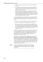
Transmit a previously built data frame on to the CAN-Bus (type 25): 

When parameter 08 is set to 25, P118 will cause the datalogger to tell the SDM-
CAN to transmit a previously ‘built’ data frame which is stored in the memory 
buffer for this packet ID (see data types 7..18 above). 

The length of the data frame transmitted is determined by 


parameter 10. If 

number of bits is less than a complete number of full bytes (1-8) then the number 
of bytes sent will be rounded up and all unused bits will be set to zero.  

The data start bit position will normally be set to one so the data frame starts at the 
beginning of the memory buffer. However, you can enter a value greater than one 
to allow part of the buffer to be transmitted, which can simplify some binary 
masking operations. 

The memory buffer is left unchanged after transmission. 

Set-up previously built data frame as a Remote Frame Response (type 26):


When parameter 08 is set to 26, P118 will configure the SDM-CAN to use a 
previously ‘built’ data frame as remote frame response for packets of the specified 
ID. The length and start positions are specified as for data type 25. 

Read error counters (type 27): 

This will return 4 values, in successive input locations starting at the location set 
by parameter 12, which show certain errors the SDM-CAN has recorded. The 
errors are written in the following order: transmit, receive, overrun and watchdog 
counts. Each is a count from 0 to 255. 

The transmit, receive and overrun counters are measures of the errors on the CAN-
Bus network as defined by the CAN standards. If the transmit counter reaches 255 
then the CAN device goes into a ‘bus-off’ state, where it effectively disconnects 
itself from the network. 

If the SDM-CAN switches to the ‘bus-off’ state, any further reads of the error 
counters will show the transmit counter fixed at 127. The counters then need to be 
reset to enable further use of the SDM-CAN (see data type 28, below). If this 
situation occurs on a regular basis, firstly check the datalogger program (P118 
parameters). If these are correct, check the structure and design of the network. 

The watchdog counter only increments (and is automatically reset) when the 
SDM-CAN ‘crashes’ either due to an internal software error or a hardware fault. 
Please contact Campbell Scientific for further advice.  

Read and reset the error counters (type 28): 

This functions in exactly the same way as type 27 except that after reading the 
error counters they are reset to zero. This will also re-enable the SDM-CAN 
interface to the CAN-Bus if it has automatically entered the ‘bus-off’ state.  

When the counters are reset, the CAN controller chip enters a special state and 
waits until it sees a period equal to 11 successive bits of inactivity on the CAN-
Bus before it returns to the normal ‘on-line’ state. Therefore this function should 
not be called too frequently otherwise data may be lost.  

3-9 

Содержание SDM-CAN

Страница 1: ...SDM CAN CAN Bus Interface User Guide Issued 26 6 07 Copyright 2001 2007 Campbell Scientific Ltd CSL 419...

Страница 2: ......

Страница 3: ...lieu of all other guarantees expressed or implied including those of suitability and fitness for a particular purpose Campbell Scientific is not liable for consequential damage Please inform us before...

Страница 4: ......

Страница 5: ...ced Programming Techniques 3 12 3 4 1 Interrupts Using the I O Connection 3 12 3 4 2 Group Trigger 3 14 3 5 Program Examples 3 14 3 5 1 Reading CAN Data 3 14 3 5 2 Simple CAN Data Transmission 3 15 3...

Страница 6: ...N Data Frames and Data Encoding and Decoding D 1 Figures 1 1 SDM CAN CAN Bus Interface 1 1 2 1 SDM CAN Internal Jumpers 2 3 2 2 SDM CAN Isolation enabled 2 3 2 3 SDM CAN Isolation disabled 2 4 2 4 Usi...

Страница 7: ...the standards to which a network claims to comply Campbell Scientific cannot provide full technical support in the understanding and decoding of data on all types of CAN networks Figure 1 1 SDM CAN CA...

Страница 8: ...applications All configuration of the interface is specified within the user s datalogger program LED status flash at power up Additional I O port for signalling to the datalogger that data is availab...

Страница 9: ...isolated CAN driver circuits by an external source the current drain by the SDM CAN is approximately 50 mA lower than the figures quoted above Typical active current non isolated with the CAN Bus in t...

Страница 10: ......

Страница 11: ...set to match the commands in the datalogger program relevant to each interface The SDM address switch can be set to 1 of 16 addresses The factory set address is 00 Table 1 shows switch position and t...

Страница 12: ...if a converter is not used power must be provided from elsewhere see below The default setting is for the converter to be OFF although for many applications you may need to turn it on once you have c...

Страница 13: ...non isolated CAN Bus interface The jumper block can be removed and rotated so that the red bar is nearest to the mode arrow head The default is for isolation enabled The CAN Bus termination impedance...

Страница 14: ...h allow access to the SDM function as well as retaining normal function of the serial port please contact your local sales office for further details The SDM CAN requires a nominal 12V power supply co...

Страница 15: ...ground Where multiple SDM devices are in use connect them in parallel to datalogger SDM ports making sure each device has a unique SDM address Ensure that the maximum cable length between the datalogg...

Страница 16: ...3 way screw terminal is marked as G H L on the SDM CAN case where G Ground H CAN High L CAN Low The CIA 9 pin D connector pin configuration is shown in Table 2 3 Table 2 3 CIA CAN Connector Pin Conne...

Страница 17: ...ping into CAN networks and also recommend maximum lengths for T s or stubs off the network For instance at the highest baud rate of 1Mbit s ISO11898 recommends a maximum bus length of 40 m and a maxim...

Страница 18: ......

Страница 19: ...se parameters otherwise either no data will be received or you risk corrupting data on the bus if the SDM CAN is enabled for transmission The next common function is to read data back from the SDM CAN...

Страница 20: ...including the speed of the datalogger in question the program it is running how many SDM devices are in use and to a lesser degree other tasks it is running e g communications activity In practise for...

Страница 21: ...ng built However if your program tries to send frames too quickly before earlier frames are sent the frames will be overwritten and lost This scenario generally does not happen with CR10X CR23X logger...

Страница 22: ...etworks the relationship between some of these parameters is predefined and just one parameter the baud rate is quoted For maximum flexibility though the user is given access to all of the relevant pa...

Страница 23: ...CAN samples the data bit and is known as tTSEG1 The final segment is known as phase segment two or tTSEG2 The relationship between these times is summarised by tbit tq tTSEG1 tTSEG2 tTSEG1 in seconds...

Страница 24: ...st ID parameter parameter 05 sets bits 0 10 entered as a number between 0 and 2047 This parameter also determines whether an 11 bit or a 29 bit Identifier is set If you index this parameter then an 11...

Страница 25: ...ich data is encoded or decoded Within a byte the MSBit is always first on the left Where the number of values parameter parameter 11 is greater than one the same function is applied to successive sect...

Страница 26: ...Data type 13 Unsigned integer most significant byte 1st 14 Unsigned integer least significant byte 1st 15 Signed integer most significant byte 1st 16 Signed integer least significant byte 1st 17 4 byt...

Страница 27: ...are written in the following order transmit receive overrun and watchdog counts Each is a count from 0 to 255 The transmit receive and overrun counters are measures of the errors on the CAN Bus netwo...

Страница 28: ...is not involved in bus activities One of the error counters is equal to or greater than 96 See data type 28 above for details of the error counters and how to reset them Read the signature and version...

Страница 29: ...received correctly from an external node are acknowledged 2 Self reception A frame transmitted from the SDM CAN that was acknowledged by an external node will also be received by the SDM CAN but no re...

Страница 30: ...nd so the SDM CAN supports both methods of referencing the start point By default the SDM CAN follows the ISO standard and the LSB is referenced to the right most bit of the frame The bit number can r...

Страница 31: ...ckets as possible In this case the interrupt facility can be used to give capture of the CAN data as a higher priority over the normal scheduled measurement tasks allowing the data to be captured at t...

Страница 32: ...liseconds If the I O terminal is held at 5V by another peripheral it will wait until the I O terminal goes low and has been low for 50 milliseconds before trying to drive it high to 5V again The I O l...

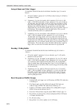
Страница 33: ...g and triggering Operating systems V3 include the ability for the user data logger program to attach a buffer of 256 frames to any receiving CAN ID up to a limit of 25 different ID s If the user progr...

Страница 34: ...sed to create the buffer and attach it to a particular ID Reading Polling Buffer To implement this buffer function the read switch Data type 33 is used as follows a If start bit number parameter 9 is...

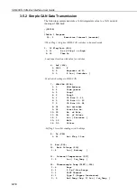
Страница 35: ...etrieve Data from CAN network 1 SDM CAN P118 1 0 SDM Address 2 4 Time Quanta 3 5 Tseg1 4 2 Tseg2 5 1024 ID Bits 0 10 for 11 bit CAN ID 6 7680 ID Bits 11 23 7 12 ID Bits 24 28 8 2 Rx unsigned int LSB 1...

Страница 36: ...ponent of 10 3 3 Z Loc Switches Send switch settings to SDM CAN 7 SDM CAN P118 1 0 SDM Address 2 2 Time Quanta 3 5 Tseg1 4 2 Tseg2 5 1 ID Bits 0 10 6 0 ID Bits 11 23 7 0 ID Bits 24 28 8 32 Set switche...

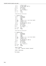
Страница 37: ...check the jumper settings inside the SDM CAN if enabling transmission as the default setting is for transmission to be disabled in hardware NOTE 3 5 3 Building and Sending Data Frames The following t...

Страница 38: ...CAN internal software switches 1 If Flag Port P91 1 11 Do if Flag 1 is High 2 30 Then Do Load input location with value for switches 2 Z F P30 1 10 F 2 0 Exponent of 10 3 3 Z Loc Switches Send switch...

Страница 39: ...ng the Group Trigger The SDM Group Trigger controls SDM devices that support the Group Trigger protocol including the SDM CAN All Group Trigger devices are triggered to make simultaneous measurements...

Страница 40: ...7 12 ID Bits 24 28 8 2 Rx unsigned int LSB 1st 9 33 Start Bit No 10 16 No of Bits 11 1 No of Values 12 2 Loc Eng_1 13 0 125 Mult 14 0 0 Offset Retrieve Data from CAN network B 8 SDM CAN P118 1 01 SDM...

Страница 41: ...CR9000 and CR5000 to allow users to run a program at more than 200Hz with the SDM CAN It gives a 5 fold improvement in performance over normal mode Block mode operation is activated by using data typ...

Страница 42: ...SEG2 ID DATATYPE STARTBIT NUMBITS NUMVALS MULT OFFSET where CANDATA is a variable or array which either holds data to be transmitted or will hold data that is to be read from the CAN Bus ADDRESS is th...

Страница 43: ...CANREP1 1 Repetitions Const ADDR1 0 SDM address of SDM CAN Module Const DTYPE1 2 Collect and retrieve data values Const STBIT1 33 Start position in data frame Const NBITS1 16 Number of bits value Con...

Страница 44: ...twork Parameters Const TQUANT 4 Set SDM CAN to 250K Const TSEG1 5 Network speed Const TSEG2 2 Data Frame Parameters ___________________________CANbus Block1_________________________ Send switch value...

Страница 45: ...nsmit Data on to CAN network CanBus TBlk1 ADDR2 TQUANT TSEG1 TSEG2 1 DTYPE2 STBIT2 NBITS2 NVALS2 CMULT2 COSET2 Next Scan Loop up for the next scan EndProg Program ends here The default setting for the...

Страница 46: ...ry 1 Secs non burst __________________________ CAN Blocks __________________________ Read status of digital I O port return value to NewData variable ReadIO NewData 7 B1 When digital I O port is high...

Страница 47: ...t three Carriage Returns so the SDM CAN can recognise the baud rate at which you are communicating As soon as your baud rate has been detected the SDM CAN will return the prompt CAN to your terminal w...

Страница 48: ...hen be set to and stay at this baud rate until the changed by the datalogger following a re compilation of the program by the user or by a datalogger SDM communications error which will force the SDM...

Страница 49: ...and the 3rd n is number of frame buffers Bus mode indicates the following states 0 Bus On the SDM CAN is involved in bus activities Error counters are less than 96 1 Bus On the SDM CAN is involved in...

Страница 50: ...nnected to a datalogger To load the new operating system take the following steps Run the CSOS software and set up the communications parameters to specify the COM port to which the SDM CAN is connect...

Страница 51: ...as which data type to use which Buffer Set it should get the data from and where its New data flag is located plus a large amount of other information The New data flags are set when new data arrives...

Страница 52: ...is ready for transmission The SDM CAN will scan the buffers checking this flag in each buffer that is set for transmission When it finds a flag that is set it will first check if the transmitter is b...

Страница 53: ...ta frame unsigned integer MSB first OR ed 14 Build data frame unsigned integer LSB first OR ed 15 Build data frame signed integer MSB first OR ed 16 Build data frame signed integer LSB first OR ed 17...

Страница 54: ...equest 32 Set SDM CAN s internal switches Switch Code Description A 0 Not used B 0 returns the last value captured default 1 returns 99999 if value already read by datalogger C 0 Disable interrupts de...

Страница 55: ...ield 1 bit DP Data Page Field 1 bit PF PDU Format Field 8 bits PS PDU Specific Field 8 bits SA Source Address Field 8 bits Table C 1 Mapping of the J1939 Fields into a 29 Bit Identifier Bit 28 27 26 2...

Страница 56: ...1 87654321 Details of specific data frame values can be found in the SAE J1939 standard NOTE C 4 Retrieving J1939 Accelerator Pedal Position Data using a CR9000 CR5000 Bus Speed 250k Baud C 4 1 Encodi...

Страница 57: ...4321 87654321 87654321 87654321 87654321 87654321 87654321 The start bit for this value is 49 as it is the least significant bit of the data value within the data frame that this parameter refers to A...

Страница 58: ...urrent system constraints the ID parameter must be entered directly into the CanBus instruction NOTE C 5 Retrieving J1939 Accelerator Pedal Position Data using a CR23X CR10X Bus Speed 250k Baud C 5 1...

Страница 59: ...nverted to 768010 and used as the second ID parameter The third value is made up of bits 24 28 which is 011002 this is converted to 1210 and used as the third ID parameter C 5 2 Finding the Start Bit...

Страница 60: ...SDM CAN CAN Bus Interface User Guide 13 0 125 Mult 14 0 0 Offset Table 2 Program 02 0 0000 Execution Interval seconds Table 3 Subroutines End Program C 6...

Страница 61: ...4 For the Left Hand Reference some manufacturers may number the bits in the following order Left Hand Ref 8 1 16 9 24 17 32 25 40 33 48 41 56 49 64 57 An additional variation is that sometimes the bit...

Страница 62: ...ss 2 1 Time quanta 3 5 Tseg1 4 4 Tseg2 5 1001 ID Bits 0 10 6 0000 ID Bits 11 23 7 00 ID Bits 24 28 8 2 Rx unsigned int LSB 1st 9 8 Start Bit No 10 16 No of Bits 11 1 No of Values 12 1 Loc value_A 13 1...

Страница 63: ...SDM Address 2 1 Time quanta 3 5 Tseg1 4 4 Tseg2 5 1001 ID Bits 0 10 6 0000 ID Bits 11 23 7 00 ID Bits 24 28 8 2 Rx unsigned int LSB 1st 9 24 Start Bit No 10 16 No of Bits 11 2 No of Values 12 1 Loc va...

Страница 64: ...0 SDM Address 2 1 Time quanta 3 5 Tseg1 4 4 Tseg2 5 1001 ID Bits 0 10 6 0000 ID Bits 11 23 7 00 ID Bits 24 28 8 2 Rx unsigned int LSB 1st 9 12 Start Bit No 10 12 No of Bits 11 2 No of Values 12 1 Loc...

Страница 65: ...Time quanta 3 5 Tseg1 4 4 Tseg2 5 1001 ID Bits 0 10 6 0000 ID Bits 11 23 7 00 ID Bits 24 28 8 4 Rx signed int LSB 1st 9 4 Start Bit No 10 12 No of Bits 11 1 No of Values 12 1 Loc value_A 13 1 0 Mult 1...

Страница 66: ...d reference 2 SDM CAN P118 1 00 SDM Address 2 1 Time quanta 3 5 Tseg1 4 4 Tseg2 5 1001 ID Bits 0 10 6 0000 ID Bits 11 23 7 00 ID Bits 24 28 8 6 Rx real IEEE4 LSB 1st 9 16 Start Bit No 10 32 No of Bits...

Страница 67: ...eg1 4 4 Tseg2 5 1001 ID Bits 0 10 6 0000 ID Bits 11 23 7 00 ID Bits 24 28 8 1 Rx unsigned int MSB 1st 9 16 Start Bit No 10 16 No of Bits 11 1 No of Values 12 1 Loc value_A 13 1 0 Mult 14 0 0 Offset 32...

Страница 68: ...SDM Address 2 1 Time quanta 3 5 Tseg1 4 4 Tseg2 5 1001 ID Bits 0 10 6 0000 ID Bits 11 23 7 00 ID Bits 24 28 8 3 Rx signed int MSB 1st 9 32 Start Bit No 10 16 No of Bits 11 2 No of Values 12 1 Loc valu...

Страница 69: ...ference 2 SDM CAN P118 1 00 SDM Address 2 1 Time quanta 3 5 Tseg1 4 4 Tseg2 5 1001 ID Bits 0 10 6 0000 ID Bits 11 23 7 00 ID Bits 24 28 8 1 Rx unsigned int MSB 1st 9 24 Start Bit No 10 12 No of Bits 1...

Страница 70: ...quanta 3 5 Tseg1 4 4 Tseg2 5 1001 ID Bits 0 10 6 0000 ID Bits 11 23 7 00 ID Bits 24 28 8 1 Rx unsigned int MSB 1st 9 16 Start Bit No 10 12 No of Bits 11 1 No of Values 12 1 Loc value_A 13 1 0 Mult 14...

Страница 71: ...Rx real IEEE4 MSB 1st 9 1 Start Bit No 10 32 No of Bits 11 1 No of Values 12 1 Loc value_A 13 1 0 Mult 14 0 0 Offset Start bit parameter 09 Left Hand reference 2 SDM CAN P118 1 00 SDM Address 2 1 Tim...

Страница 72: ......

Страница 73: ......

Страница 74: ...ll Scientific Canada Corp CSC 11564 149th Street NW Edmonton Alberta T5M 1W7 CANADA www campbellsci ca dataloggers campbellsci ca Campbell Scientific Ltd CSL Campbell Park 80 Hathern Road Shepshed Lou...

Отзывы: