SDM-CAN CAN-Bus Interface User Guide
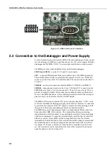
Figure 2-3 SDM-CAN Isolation disabled
2.3 Connection to the Datalogger and Power Supply
To allow communication between the SDM-CAN and a datalogger, firstly connect
it to the datalogger’s SDM port, and then connect to a 12V power supply. Both the
datalogger and the SDM-CAN 12V power supply must share a common ground.
The SDM port is provided in different ways on different dataloggers:
CR10X and CR23X
– use the C1, C2 and C3 control ports.
CR7
– a special SDM terminal block is provided as part of the SDM upgrade kit.
This terminal block is fitted on a small module adjacent to the 9 way ‘Serial I/O’
connector on the front of the 700 control module. The connections are labelled C1,
C2 and C3.
CR5000
– use the port connections labelled SDM-C1, SDM-C2 and SDM-C3.
CR9000
– connections are made via the 9 way, ‘CSI Serial I/O’ connector on the
9080 PAM card. Pins 6, 7 and 8 are used as C3, C2 and C1 respectively. Pin 2 is
ground. Campbell Scientific offers connection modules for this port which allow
access to the SDM function as well as retaining normal function of the serial port,
please contact your local sales office for further details.
The SDM-CAN requires a nominal 12V power supply connection (7-26V) rated
at 150mA. Normally the datalogger supply can be used for this feed. A connection
to ground is also required. If the 12V supply is separate from the datalogger, both
the ground of the supply and datalogger must be connected together.
The SDM and power connections are made to a black terminal block on the left-
hand side of the SDM-CAN interface. This terminal block has special spring
loaded terminals which are simple to use and highly resistant to loosening in high
vibration environments. To open the terminal simply insert the tip of a small flat
blade screw driver (3mm width) into the rectangular hole above the circular
terminal hole. Push in the blade of the screwdriver until the spring is released and
the terminal opens. Insert the pre-stripped wire and then remove the screwdriver.
See Figure 2-4. If space is limited, as when the unit is mounted in an enclosure
etc., the screwdriver can be inserted into the front of the terminal block to push
open the spring, as shown in Figure 2-5.
2-4


