Section 9. Maintenance — Details
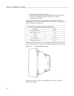
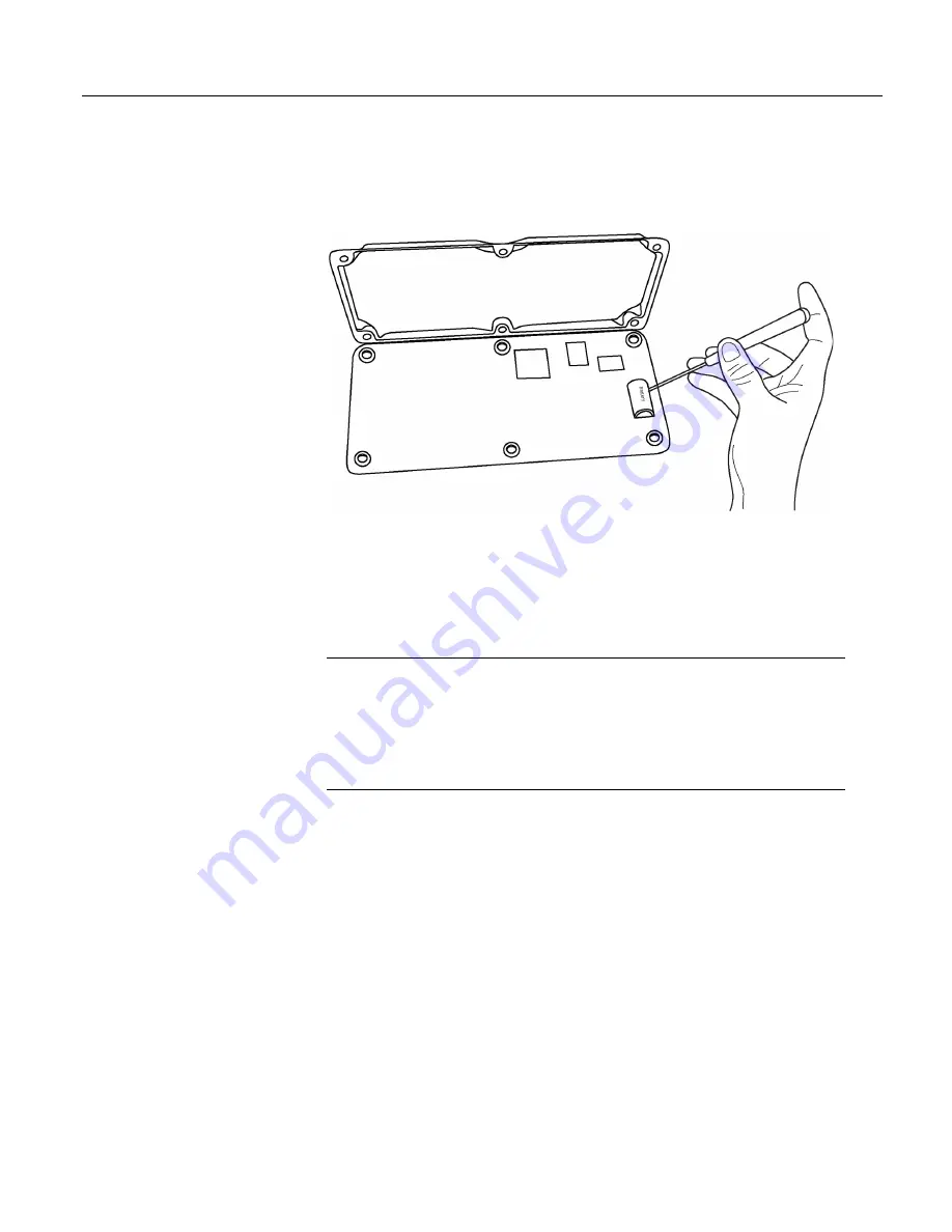
Remove six nuts, then open the clam shell.
Figure 130.
Remove and Replace Battery
Remove the lithium battery by gently prying it out with a small flat point
screwdriver. Reverse the disassembly procedure to reassemble the CR1000.
Take particular care to ensure the canister is reseated tightly into the three
connectors.
9.3
Factory Calibration or Repair Procedure
Related Topics
•
Auto Calibration — Overview
(p. 92)
•
Auto Calibration — Details
(p. 344)
•
Auto-Calibration — Errors
(p. 490)
•
Offset Voltage Compensation
(p. 323)
•
Factory Calibration
(p. 94)
•
Factory Calibration or Repair Procedure
(p. 476)
If sending the CR1000 to Campbell Scientific for calibration or repair, consult
first with a Campbell Scientific application engineer. If the CR1000 is
malfunctioning, be prepared to perform some troubleshooting procedures while
on the phone with the application engineer. Many problems can be resolved with
a telephone conversation. If calibration or repair is needed, the following
procedures should be followed when sending the product:
Products may not be returned without prior authorization. The following contact
information is for US and International customers residing in countries served by
Campbell Scientific, Inc. directly. Affiliate companies handle repairs for
customers within their territories. Please visit
www.campbellsci.com
to determine
which Campbell Scientific company serves your country.
To obtain a Returned Materials Authorization (RMA), contact CAMPBELL
SCIENTIFIC, INC., phone (435) 227-2342. After an application engineer
determines the nature of the problem, an RMA number will be issued. Please
write this number clearly on the outside of the shipping container. Campbell
476
Содержание CR1000
Страница 2: ......
Страница 4: ......
Страница 6: ......
Страница 32: ......
Страница 36: ......
Страница 38: ......
Страница 40: ......
Страница 60: ...Section 4 System Quickstart Figure 16 PC200W View Line Graph 60 ...
Страница 96: ......
Страница 98: ...98 ...
Страница 302: ......
Страница 350: ...Section 8 Operation Figure 91 Pulse Sensor Output Signal Types Figure 92 Switch Closure Pulse Sensor 350 ...
Страница 453: ...Section 8 Operation Figure 115 Using the Keyboard Display 453 ...
Страница 454: ...Section 8 Operation 8 8 1 Data Display Figure 116 Displaying Data with the Keyboard Display 454 ...
Страница 456: ...Section 8 Operation Figure 118 Real Time Custom 456 ...
Страница 457: ...Section 8 Operation 8 8 1 3 Final Memory Tables Figure 119 Final Memory Tables 457 ...
Страница 458: ...Section 8 Operation 8 8 2 Run Stop Program Figure 120 Run Stop Program 458 ...
Страница 460: ...Section 8 Operation Figure 122 File Edit 460 ...
Страница 461: ...Section 8 Operation 8 8 4 PCCard Memory Card Display Figure 123 PCCard CF Card Display 461 ...
Страница 478: ......
Страница 506: ......
Страница 536: ......
Страница 636: ......
Страница 642: ......
Страница 644: ......
Страница 676: ......
Страница 677: ......


