


229 Heat Dissipation Matric Water Potential Sensor
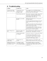
8. Troubleshooting
Symptom Possible
Cause
Action
Temperature reading is
offscale (-6999 or NAN)
Thermocouple wire not
connected to correct
datalogger channel
Check program to see which differential input
channel 229 should be connected to and verify that it
has a good connection to that channel
Break in thermocouple wire
Use ohm-meter to measure resistance between blue
and red wires. The reading in ohms should be
approximately the cable length in feet. An open
circuit indicates a break in the wire
Multiplexer not operating
properly
Make sure that multiplexer has 12V between 12V
and GND terminals.
Check for a good electrical connection on the wires
that connect RES and CLK to datalogger control
ports.
Check for a good electrical connection on the wires
going from the common channels to the datalogger
and the current excitation module.
Check program to make sure that the control port
connected to RES is being set high and the control
port connected to CLK is being pulsed.
DeltaT reading close to
zero
Heater wire broken or not
properly connected
Check resistance between terminal screws for green
and black wires. It should read 34 - 40 ohms.
Current excitation module
not turning on
Check for 12V b12V and ground terminals
Check for good electrical connection on wire
connecting CTRL with datalogger control port
Check program to make sure that control port
connected to CTRL is being set high
Temperature decreases
during heating
Thermocouple wires
reversed
Make sure blue wire is on the high side of the
differential input channel and red is on the low side
Readings for first sensor
on multiplexer are all right,
but all others read zero
All readings are being
written to the same input
location (Edlog dataloggers)
Check program to make sure measurement
instructions in the multiplexer loop are indexed
(-- next to the input location number. Press F4 or C
to toggle the --)
27
Содержание 229
Страница 33: ......


