Campbell 229 Скачать руководство пользователя страница 15

229 Heat Dissipation Matric Water Potential Sensor 

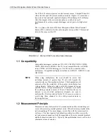
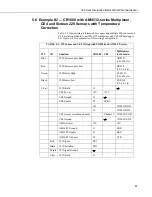
5.6  Example #2 — CR1000 with AM16/32-series Multiplexer, 

CE4 and Sixteen 229 Sensors with Temperature 
Correction 

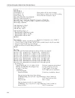
Table 5-2 shows wiring information for connecting multiple 229 sensors and 
CE4 excitation module to an AM16/32 multiplexer and CR1000 datalogger.  
See Figure 6-4 for a schematic of this wiring configuration.  

TABLE 5-2.  229 Sensor and CE4 Wiring with CR1000 and AM16/32-series 

 
229  

 
107 

 
Function 

 
CR1000 

 
CE4 

Multiplexer 
(4x16 mode) 

Blue 


229 Thermocouple High 


ODD H 
(1H, 3H, etc) 

Red 


229 Thermocouple Low 


ODD L 
(1L, 3L, etc) 

Green   

229 Heater High 


EVEN H 
(2H, 4H, etc) 

Black   

229 Heater Low 


EVEN L 
(2L, 4L, etc) 

Clear  

229 

Shield 


   CE4 

Power 

12V 

+12V 


   CE4 

Ground 


   CE4 

Enable 

C3 CTRL 


1H  

COM 

ODD 


1L 


COM ODD L 


CE4 current excitation channel   

Channel 1  COM EVEN H 

   CE4 

Ground 


COM EVEN L 

   AM16 

Power 

12V 


12V 

   AM16/32 

Ground 

G   

GND 

   AM16/32 

Enable 

C1  

RES 

   AM16/32 

Advance 

C2  

CLK 


Red 

107 Signal 

SE 3 


 Black 

107 

Excitation 

EX1 


 Purple 

107 

Signal 

Ground 


 Clear 

107 

Shield 

G   


11 

Содержание 229

Страница 1: ...229 Heat Dissipation Matric Water Potential Sensor Revision 5 09 C o p y r i g h t 2 0 0 6 2 0 0 9 C a m p b e l l S c i e n t i f i c I n c...

Страница 2: ...iding in countries served by Campbell Scientific Inc directly Affiliate companies handle repairs for customers within their territories Please visit www campbellsci com to determine which Campbell Sci...

Страница 3: ...ger Program Structure and Multiplexers 7 5 4 Temperature Correction 8 5 5 Example 1 CR1000 with CE4 and Four 229s 9 5 6 Example 2 CR1000 with AM16 32 series Multiplexer CE4 and Sixteen 229 Sensors wit...

Страница 4: ...for Typical Calibration 20 6 2 Measurement error for range of soil temperatures and wide range of matric potential 22 6 3 Measurement error for range of soil temperatures and wetter range of matric po...

Страница 5: ...with epoxy FIGURE 1 1 A 229 Heat Dissipation Matric Water Potential Sensor is shown at the top The hypodermic assembly without epoxy and ceramic is shown just below Cutaway view shows longitudinal sec...

Страница 6: ...multiplexers the user should be aware that switching currents of greater than 30 mA will degrade the contact surfaces of the mechanical relays This degradation will adversely affect the suitability o...

Страница 7: ...ry Figure 1 3 presents a typical temperature response in a silt loam the ceramic water complex approaches a constant value When a constant power is dissipated from the line heat source the tempera inc...

Страница 8: ...1 x 2 7 cm 1 1 CE8 16 5 cm 6 5 x 5 4 cm 2 1 x 2 7 cm 1 1 ght CE4 131 g 4 6 oz CE8 184 g 6 5 oz 3 Installation 3 1 Orientation For best measurement results the 229 should be installed horizontally at t...

Страница 9: ...ntial between the 229 ceramic an surrounding soil the sooner equilibrium will be reached Filling th Simple immersion of the sensors in water can leave some entrapped air in pores Complete saturation c...

Страница 10: ...en used as a thermocouple reference A thermocouple circuit voltage potential is affected by the temperature of all dissimilar metal junctions When using a multiplexer with the 229 sensor the temperatu...

Страница 11: ...s Since all of the output channels of the CE4 or CE8 are activated when the control terminal is set high power will be applied to all of the 229 sensors connected to the current source Inaccurate meas...

Страница 12: ...ex the 50 mA excitation for the 229 L sensors in order to avoid using those channels for low voltage measurements in future applications NOTE 5 4 Temperature Correction The rise in temperature over th...

Страница 13: ...ent excitation module TABLE 5 1 Wiring for Four 229s with CR1000 and CE4 229 CR1000 229 CE4 229 1Blue 1H 229 1 Green Channel 1 229 1Red 1L 229 1 Black 229 2Blue 2H 229 2 Green Channel 2 229 2Red 2L 22...

Страница 14: ...efore heating TCDiff StartTemp_C Num229 mV2_5C 1 TypeT RefTemp_C True 0 _60Hz 1 0 PortSet 1 1 Set C1 high to activate CE4 Delay 0 1 Sec Wait 1 second Measure temperature after 1 second of heating TCDi...

Страница 15: ...Wiring with CR1000 and AM16 32 series 229 107 Function CR1000 CE4 Multiplexer 4x16 mode Blue 229 Thermocouple High ODD H 1H 3H etc Red 229 Thermocouple Low ODD L 1L 3L etc Green 229 Heater High EVEN H...

Страница 16: ...each probe these are examples dTdry 1 3 421 dTdry 2 3 417 dTdry 3 3 433 dTdry 4 3 418 dTdry 5 3 412 dTdry 6 3 407 dTdry 7 3 422 dTdry 8 3 428 dTdry 9 3 399 dTdry 10 3 377 dTdry 11 3 405 dTdry 12 3 40...

Страница 17: ...les and Store Data Flag 1 False Disable 229 measurements NextScan EndProg 5 7 Example 3 CR10X with 229 Sensor Table 5 3 shows wiring information for reading a single sensor with a CR10X datalogger CE4...

Страница 18: ...6 0 0 Offset 4 Thermocouple Temp DIFF P14 Measure initial sensor temperature 1 1 Reps 2 1 2 5 mV Slow Range 3 1 DIFF Channel 4 1 Type T Copper Constantan 5 1 Ref Temp Deg C Loc Ref_Temp 6 2 Loc Tinit_...

Страница 19: ...stantan 5 1 Ref Temp Deg C Loc ref_temp 6 4 Loc T30sec_1 7 1 0 Mult 8 0 0 Offset 10 Do P86 turn off CE8 1 52 Set Port 2 Low 11 Z X Y P35 Calculate delta T 1 4 X Loc T30sec_1 2 3 Y Loc T1sec_1 3 5 Z Lo...

Страница 20: ...e High ODD H 1H 3H etc Red 229 Thermocouple Low ODD L 1L 3L etc Green 229 Heater High EVEN H 2H 4H etc Black 229 Heater Low EVEN L 2L 4L etc Clear 229 Shield G CE4 CE8 Power 12V 12V CE4 CE8 Ground G C...

Страница 21: ...Loop P87 Loop of 16 for 16 sensors on AM16 32 1 0 Delay 2 16 Loop Count 6 Do P86 Advance to next multiplexer channel 1 73 Pulse Port 3 7 Temp 107 P11 Measure reference temperature 1 1 Reps This is th...

Страница 22: ...IFF P14 read temperature after 30 seconds heating 1 1 Reps 2 21 10 mV 60 Hz Reject Slow Range 3 1 DIFF Channel 4 1 Type T Copper Constantan 5 2 Ref Temp Deg C Loc Tref_C 6 35 Loc T30s_1 7 1 0 Mult 8 0...

Страница 23: ...unctional expression of the relationship can take several forms The most commonly used function is exp T 1 with the soil water potential exp the exponential function T the temperature increase during...

Страница 24: ...n temperature during measurement when the 229 sensor is dry dry T wet T is the change in temperature during measurement when the 229 sensor is fully saturated and T is the change in temperature during...

Страница 25: ...surement If the soil temperature when the e onductivity of the ceramic The thermal conductivity of the ceramic depends on the combination rts t soil 2 r Soil Temperature The heat dissipatio temperatur...

Страница 26: ...500 1000 1500 2000 600 400 200 0 200 400 600 10 degrees C 16 degrees C 18 degrees C 22 degrees C 24 degrees C 30 degrees C matric potential kPa error kPa FIGURE 6 2 Measurement error for range of soi...

Страница 27: ...e work of Flint et al 2002 To implement the correction normalized temperature must be used for the calibration variable Normalized temperature is as defined in equation 3 The correction procedure is a...

Страница 28: ...d for the soil water to leave the sample system depends on the pressure gradient and the hydraulic conductivity of the soil and the porous bottom plate Equilibration of water potential throughout the...

Страница 29: ...ve to be depressurized and opened for each reading A temporary connector can be used to disconnect the datalogger from the other components installed in the pressure vessel Pressurized readings can be...

Страница 30: ...ion 7 Maintenance The 229 does not require maintenance after it is installed in the soil The datalogger current excitation module and multiplexer if used should be kept in a weatherproof enclosure Per...

Страница 31: ...urrent excitation module Check program to make sure that the control port connected to RES is being set high and the control port connected to CLK is being pulsed DeltaT reading close to zero Heater w...

Страница 32: ...pbell K M Ellett and C Calissendorff 2002 Calibration and Temperature Correction of Heat Dissipation Matric Potential Sensors Soil Sci Soc Am J 66 1439 1445 Reece C F 1996 Evaluation of a line heat di...

Страница 33: ......

Страница 34: ...a Corp CSC 11564 149th Street NW Edmonton Alberta T5M 1W7 CANADA www campbellsci ca dataloggers campbellsci ca Campbell Scientific Centro Caribe S A CSCC 300 N Cementerio Edificio Breller Santo Doming...

Отзывы: