p.
2
4
24
-
M
an
u
al
c
od
e:
11
9
G
F
8
8
11
9
G
F
8
8
ve
r.
1
.0
1.
0
0
5
/2
0
12
© C
A
M
E C
an
ce
lli
A
uto
m
ati
ci
S
.p.
A
. - T
h
e d
ata a
n
d i
nf
or
m
ati
on i
n th
is
m
an
u
al
m
ay b
e u
p
d
ate
d at a
ny ti
m
e by C
am
e C
an
ce
lli
A
uto
m
ati
ci
S
.p.
A
. w
h
ic
h i
s u
n
d
er n
o o
b
lig
ati
on
to n
otify s
ai
d u
p
d
ate
s.
ENGLISH
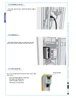
11.5 ETHERNET connection
11.6 Switching on
11.7 Status signal LED
- At the lower end of the post, connect the Ethernet cable to
its socket.
- Once all electrical connections are made, to start the entry
and exit units press the switch on the left side of the unit.
There is an LED light atop the entry and exit units to show colour-
coded status.
- Blue with changing brightness_Standing by;
- Blue_Active with vehicle present
- White_Undergoing maintenance
- Red fl ashing_Out of order/Alarm
Status signal LED


