


-8-
I
T
ALIANO—ENGLISH—ESP
AÑOL
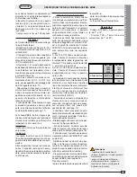
TECHNICAL DESCRIPTION ZBK - ZBKE MOTHERBOARD
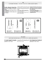
This control board is powered across
terminals L1 and L2, and is protected
by fuse on the main power line (see
table).
Control systems are powered by low
voltage and protected with by a 2A
fuse.
The total power consumption of 24 V
accessories must not exceed 20W.
Fixed operating time of 150 seconds.
Safety
Photocells can be connected to obtain:
- Re-opening during the closing cycle
(2-C1);
- Re-closing during the opening cycle
(2-CX, see dip 8-9);
- Partial stop, shutdown of moving gate,
with activation of an automatic closing
cycle (2-CX, see dip 8-9);
- Total stop (1-2), shutdown of gate
movement without automatic closing;
a pushbutton or radio remote control
must be actuated to resume move-
ment;
Note: If an normally closed safety con-
tact (2-C1, 2-CX, 1-2) is opened, the
LED (n°11) will flash to indicate this fact;
- Obstacle presence detection. When
the motor is stopped (gate is closed,
open or half-open after an emercency
stop command), the transmitter and the
control pushbutton will be deactivated
if an obstacle is detected by one of the
safety devices (for example, the pho-
tocells);
- Safety test function. The control unit
will now check the safety system eve-
ry time an opening or closing command
is given (see pag. 11).
The board ZBKE, moreover, integrates
and independently runs a safety func-
tion capable of detecting obstacles that
hinder movement:
during opening
the gate stops and the automatic clo-
sure is activated;
during closure
the gate inverts its direction until it is
completely open, after which it closes
automatically.
Warning! after three consecutive inver-
sions, the gate will remain open and
automatic closure will be discontinued.
To close the gate, use the radio remote
control or the push-button.
Other functions
- Automatic closing: The automatic
closing timer is automatically activat-
ed at the end of the opening cycle. The
preset, adjustable automatic closing
time is automatically interrupted by the
activation of any safety system, and
is deactivated after a STOP command
or in case of power failure;
- Partial opening. Opening of the gate
to allow for foot traffic; activated by
connecting to terminals 2-3P and ad-
justed with the AP-PARZ. trimmer. With
this function, the automatic closing can
vary in the following way:
1) Dip 12 set to ON: after a partial open-
ing, the time for automatic closing func-
tions independently of the adjustment
of the TCA trimmer and of the position
of Dip 1; it is set at 8 seconds.
2) Dip 12 set to OFF: after a partial
opening, the time for automatic clos-
ing is adjustable only if Dip 1 is set to
ON.
- Cycle lamp. The lamp which lights the
manoeuvring zone: it remains lit from
the moment the doors begin to open
until they are completely closed (includ-
ing the time required for the automatic
closure). In case automatic closure is
not enabled, the lamp remains lit only
during movement (E-EX);
- Courtesy Light. A light that illuminates
the manoeuvring zone; after an open-
ing command, the light remains on for
a fixed time of 5 minutes and 30 sec-
onds (E-EX, see page 12);
- "Operator present" function: Gate op-
erates only when the pushbutton is held
down (the radio remote control system
is deactivated);
- Pre-flashing for 5 seconds, while the
door is opening and closing;
- Master function; the panel assumes
all the command functions when two
paired motors are used (see page 18);
- Slave function; this panel is exclu-
sively controlled by the “MASTER” (see
p. 18);
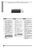
- Enabling functions of partial-stop or
re-closure during opening; normally-
closed contact (2-CX), select one of the
two functions by setting dip, see se-
lection of functions;
- Programming the calibration of the
electronic opening and closing limit
switches for the ZBKE panel (see p.
15),
Type of command:
- open-close-reverse by button and
transmitter;
- open-stop-close-stop by button and
transmitter;
- open only by transmitter.
Adjustments
- Trimmer AP.PARZ. = Partial opening:
1" to 14";
- Trimmer TCA = Automatic closing time:
1" to 150";
ENGLISH
BK / BKE
1200
1800
2200
BK / BKE
1210
1810
2210
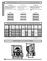
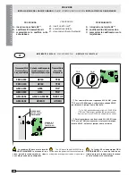
Power supply
230V a.c.
120V a.c.
Line fuse
8A
15A
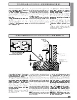
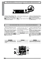
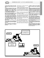
Important
- the opening of the unblock panel
arrests the motor.
- Shut off the mains power and
disconnect the batteries before
servicing the inside of the unit.