PTP 800 Series User Guide
I ndoor RF unit ( I RFU)
phn- 2513_004v000 ( Oct 2012)
1- 25
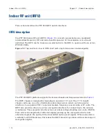
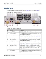
IRFU interfaces
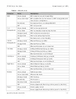
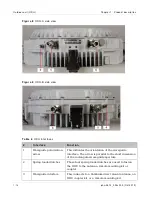
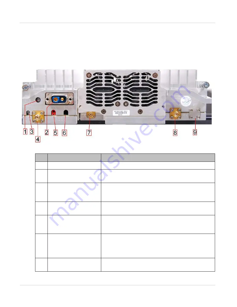
The IRFU transceiver interfaces are illustrated in
Figu r e 1 6
I RFU t ransceiver int erfaces
Ta ble 7
I RFU t ransceiver int erfaces
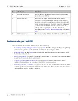
#
I n t e r fa ce
Fu n ct ion
1
Power button
For powering the transceiver on and off.
2
Power connector
For connecting the transceiver to a standard –48 V dc
telecommunications supply.
3
“Alarm” LED
For indicating the status of the IRFU. LED states and
troubleshooting actions are described in
4
CMU connector
For connecting the transceiver to the CMU via an IF
cable with SMA connectors.
5
RSSI MAIN Test Jack
For connecting a voltmeter to measure the voltage
when aligning the antenna. For more information, see
on page
6
RSSI SD Test Jack
As RSSI MAIN Test Jack, but measures the voltage
when aligning the diversity antenna in 1+1 Tx MHSB /
Rx SD configurations. Not equipped on single RX
configurations.
7
TX Connector
For connecting the transceiver (transmit) to the BU via
an RF cable with SMA connectors.
Содержание PTP 800 Series
Страница 1: ...Cambium PTP 800 Series User Guide System Release 800 05 02 ...
Страница 40: ...Licensing requirements About This User Guide 10 phn 2513_004v000 Oct 2012 ...
Страница 232: ...Limit of liability Chapter 3 Legal information 3 22 phn 2513_004v000 Oct 2012 ...
Страница 322: ...Radiation hazard assessm ent Chapter 4 Reference information 4 90 phn 2513_004v000 Oct 2012 ...
Страница 418: ...Replacing IRFU components Chapter 5 Installation 5 96 phn 2513_004v000 Oct 2012 Figure 1 1 0 IRFU components example ...
Страница 428: ...Replacing IRFU components Chapter 5 Installation 5 106 phn 2513_004v000 Oct 2012 ...
Страница 552: ...Configuring for FIPS 140 2 applications Chapter 6 Configuration and alignment 6 124 phn 2513_004v000 Oct 2012 ...
Страница 630: ...Using recovery mode Chapter 7 Operation 7 78 phn 2513_004v000 Oct 2012 ...
Страница 648: ...Glossary I V phn 2513_004v000 Oct 2012 ...

