62 SUMMA
Networked Audio Production System
Connection Information
CONNECTING TO OTHER CONSOLES/ROUTERS
Multiple Calrec Hydra2 consoles
can be connected together and to
standalone Hydra2 routers, allowing
them to share each other’s I/O
resources.
Before connecting a console to an active
Hydra2 network it is essential to be aware
of IP address compatibility and of the
Master Router status.
A single, standalone console along with its
processing core and connected I/O units,
forms a basic Hydra2 network. All Hydra2
networks require one, and only one, of
the processing cores to be configured as
the Master Router. Therefore, consoles
specified during the ordering process to
be standalone will have their processing
core pre-configured as a Master Router.
It is vital that this is changed before
connecting to an active Hydra2 network.
A console specified to be part of a wider
Hydra2 network will not function reliably
until it is connected to a network with
a Master Router, or has its own core
changed to become the Master. Please
contact Calrec support for guidance on
configuring router master/slave status.
Each processing core is configured
with a unique IP address within the
network. When connecting a console/
Master Router to an existing network it
is important to ensure that the new IP
address does not conflict with the current
IP address range used on the existing
network.
To provide redundancy, for each primary
router to router link, there should also be a
(normally inactive) link fitted between the
secondary router cards in the same cores.
When multiple cores are networked, it
is essential that they are all locked to
the same sync reference.
Each Hydra2 link can carry 512 channels
of audio simultaneously in each direction.
Bandwidth between cores can be
increased in multiples of 512 audio
channels by adding additional links to form
‘Trunk Links’.
Trunk links should only be fitted if
they have been configured. Please
contact Calrec Customer Support or
your local representative for guidance
on trunk link configuration.
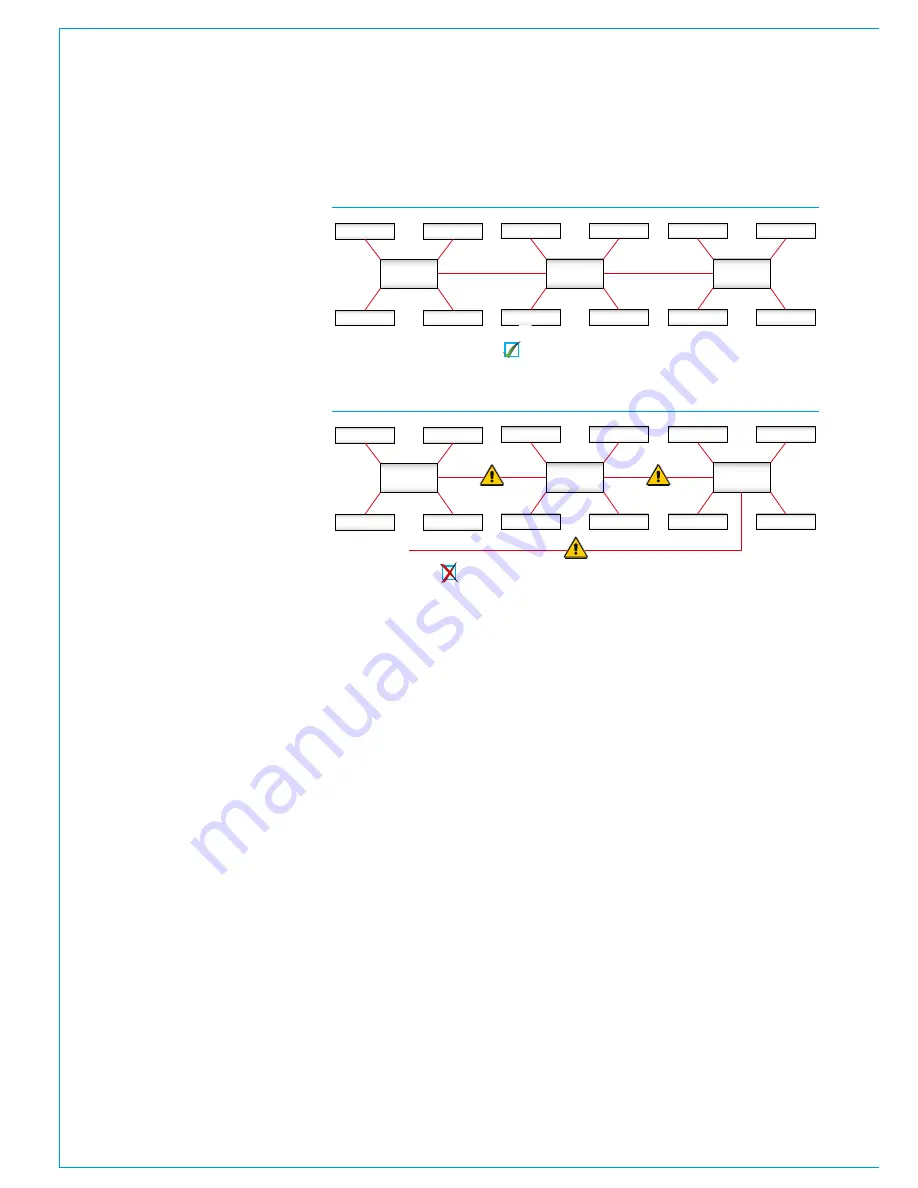
It is important that there is only one path
(not counting dedicated secondaries
and configured trunks) between any two
points on the network. It is important to
note that the path between I/O port and
console router may pass through other
routers. The second image above shows
an incorrectly connected network. Here,
the addition of a third router to router link
creates duplicate paths in the network.
This will cause network collisions as data
has the option to take two paths between
any two routers—one path is direct, the
other is via the third router. Removing
any one of the three router to router links
corrects this, effectively changing the
topology to match that shown the basic
star network shown above.
For large systems, network topology
should be considered to manage
bandwidth. Using a processing core as a
central point to connect other processing
core, rather than daisy-chaining them
together, minimises the number of cores a
signal has to pass through to get between
I/O and console, optimising the available
bandwidth of each router to router link.
Please refer to the Hydra2 installation
manual and H20 user guide for more
information regarding Hydra2 and I/O.
Router /
Processing
Core
Audio I/O
Audio I/O
Audio I/O
Audio I/O
Router /
Processing
Core
Audio I/O
Audio I/O
Audio I/O
Audio I/O
Router /
Processing
Core
Audio I/O
Audio I/O
Audio I/O
Audio I/O
Router /
Processing
Core
Audio I/O
Audio I/O
Audio I/O
Audio I/O
Router /
Processing
Core
Audio I/O
Audio I/O
Audio I/O
Audio I/O
Router /
Processing
Core
Audio I/O
Audio I/O
Audio I/O
Audio I/O
FIGURE 1 - CORRECT CONNECTION OF A THREE CONSOLE NETWORK
FIGURE 2 - INCORRECT CONNECTION OF A THREE CONSOLE NETWORK
Three router cores connected with no duplicate paths.
Incorrect connection! The additional link creates a duplicate path.
Содержание SUMMA
Страница 1: ...calrec com Putting Sound in the Picture Networked Audio Production System SUMMA INSTALLATION MANUAL...
Страница 5: ...calrec com Putting Sound in the Picture SUMMA INFORMATION...
Страница 10: ...10 SUMMA Networked Audio Production System...
Страница 11: ...calrec com Putting Sound in the Picture SUMMA GETTING STARTED...
Страница 13: ...CALREC Putting Sound in the Picture 13 SUMMA CONSOLE TO CORE CONNECTIONS 2...
Страница 25: ...calrec com Putting Sound in the Picture SUMMA CONTROL SURFACE...
Страница 27: ...CALREC Putting Sound in the Picture 27 12 8 FADER TOP VIEW 24 8 FADER TOP VIEW 875 50 mm 34 47 1308 0 mm 51 5...
Страница 28: ...28 SUMMA Networked Audio Production System Control Surface 36 FADER TOP VIEW WIDTH 1740 5 mm 68 5...
Страница 32: ...32 SUMMA Networked Audio Production System Control Surface FRONT PANEL CONNECTIONS Headphone Output...
Страница 36: ...36 SUMMA Networked Audio Production System...
Страница 37: ...calrec com Putting Sound in the Picture SUMMA PROCESSING CORE...
Страница 45: ...calrec com Putting Sound in the Picture SUMMA CONNECTION INFORMATION...
Страница 64: ...64 SUMMA Networked Audio Production System...
Страница 65: ...calrec com Putting Sound in the Picture SUMMA REMOTE CONTROL AND PRODUCTION AUTOMATION...
Страница 77: ...calrec com Putting Sound in the Picture SUMMA SETUP USER LOGGING...
Страница 82: ...82 SUMMA Networked Audio Production System...
Страница 83: ...calrec com Putting Sound in the Picture SUMMA SPECIFICATIONS...


