Entering programs and settings
Controller operation is based on an internal clock with calendar and automatic time adjustment.
By navigating through the appropriate menu items and using the buttons on the front panel (“MENU”.
“UP”
, “DOWN”
, and “OK”), the user can configure the controller, set the various parameters,
and display the temperature log.
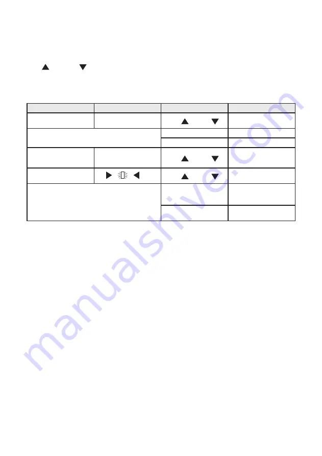
Functions of the configuration buttons
Description
Display
Button function
Effect
Menu item - arrows beside
the row
“UP”
,
“DOWN”
Moves the cursor to another
row
+OK
Opens the related submenue
Menu
Go back to previous level
Other rows available
-arrows in the screen margin
“UP”
,
“DOWN”
Displays other rows in the
menu
Parameter selection
-cursor flashing
“UP”
,
“DOWN”
Increases or descreases the
parameter value
+OK
Confirms the setting - cursor
disappears and the value
becomes actual
Menu
Return to previous level
without making changes
Whatever status the controller is in (except Low Power), navigation around the various menus to read
the various settings and view the stored log data is always possible. However, for safety purposes,
the
settings data can be modified only when the controller is in “Adjustment” mode.
In particular,
parameters can not be modified while the controller is in “disinfection”, “flux” or “thermal shock” mode,
and when the controller is in the “inactive with alarm” status. The various options are made availalble,
depending on whether the return water temperature sensor has been enabled. To set programs 1B or
2, the return water temperature sensor must be set as Present. To be able to remove the return water
temperature sensor (i.e. set it as Present of Absent), program 0 or 1A must be set first.
Remote control
The controller can be controlled from a remote computer with the RS485 serial output connection, which
can be accessed by hard-wired terminals and through the connector on the front panel. Since the interface
is the multipoint bus type it is necessary for each controller connected on the bus to be identified by
an appropriate address to avoid identification conflicts. For a detailed description of the operations and
controls that are available from a remote location using this interface, refer to the relevant documentation.
Contact Caleffi for list of registers (points) for mapping LEGIOMIX information to ModBus. Configuation,
mapping, hardware (routers, modem, etc.), and software are customer/user responsibility. Code NA10520
Modbus-to-BACnet gateway is available separately for translating ModBus to BACnet.
19


