ITC 220 Base Station Transceiver Installation Guide PN 133991 Rev. A
| Page 18
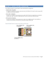
Figure 10 Narrowband RF antenna connections at the rear of the Base Station Transceiver
To connect the cables:
1.
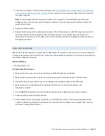
Perform or confirm the 220 MHz antenna VSWR before connecting the antenna(s) to the unit. The VSWR should
not exceed 1.5.
2.
Run the cables into the rack.
3.
Connect each antenna cable to the appropriate antenna input connector at the rear of the unit and terminate
unused connectors. (See
APPENDIX B— Possible RF Antenna Configurations
for more specific information, if
necessary.) Tighten securely, but
do not over-tighten
. Use caution to avoid cross-threading the connector.
4.
Terminate and cover unused ports with 50 Ohms termination.
6.8
CONNECT THE GPS ANTENNA
Position the GPS antenna to avoid strong interference that could saturate the antenna low-noise amplifier or the radio
GPS receiver low-noise amplifier. Combinations of strong interferers could mix and interfere directly with the GPS
signal quality. Test the transceiver GPS with any interference source active to qualify the antenna-antenna isolation of
the GPS antenna position. See
APPENDIX C— GPS Satellite Constellation Overview and Antenna Planning
Considerations
, if necessary, for reference. Because GPS satellites are not stationary, but move throughout the sky,
install the GPS antenna where it will have clear visibility to as much of the entire sky as possible. (Not just the southern
sky, as for geosynchronous satellite reception.)
The GPS antenna connection is a TNC female connector and always provides an active antenna voltage. If the active
antenna installed exceeds either the voltage or current ability of the transceiver, then external power must be supplied
to the antenna. A DC block must be used at the transceiver when the additional power is supplied, to avoid damage to
the transceiver. It is recommended that the cable length not exceed 30 meters.


