18/10/18 15
DRAWN
CHECKED
ENG APPR
MGR APPR
Classe di tolleranza*:
ISO 2768-M
*Ove non diversamente specificato
NAME
Tech. Dept.
DATE
01/10/14
NAME:
SIZE
A2
FILE NAME: asmCORRETTOnew.dft
SHEET 1 OF 1
Material:
Name?:Material
Spessore:
asmCORRETTOnew
PROJECT:
Raggio di piega
R=1.3
Cava V10
Tutte le pieghe si
intendono a 90°
dove non
diversamente
specificato
35
-4
0
mm
25-
30
mm
UKUNDA
SIG AH
Heat Recovery unit
Installation-Operation-Maintenance
reserves the right to change the specifications of the product at any time without prior notice
To prevent heat exchanger freezing, in winter, the ventila-
tion unit has anautomatic flow unbalancing system.
Temperature sensors measure the air temperature before
entering the heat exchanger and if necessary, the air flow
coming from outside is temporarily reduced.
The flow unbalance activates with downstream tem-
perature <= 3°C and the fresh air flow rate is decreased
proportionally to reach a safe temperature at the way out
the heat exchanger side exhaust air.
The maximum flow unbalance permitted is 75%.
The unbalancing cycle has a 20 minutes time duration.
For very low temperature (<-10°C) the accessory pre-
heater to heat up the outdoor air is recommended.
Protect the condensate drain from freezing in the winter
months with insulation or provide the pipe with trace
heating.
9 FROST RISK
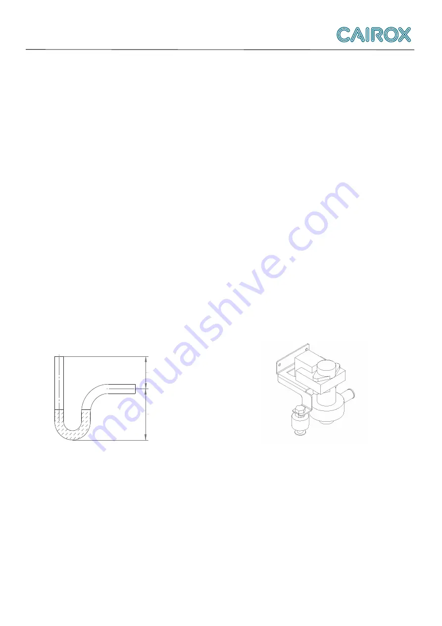
It is important that the air handling unit is installed hori-
zontally. The condensate drain must be connected to a
site drain / siphon with water trap or an on-site conden-
sate pump.
During operation there may be a negative pressure up to
500 Pa (equivalent to a 50mm water column) enter in the
flow. In this case, the difference in height must be 50mm
minimum in the siphon.
Follow the indication on illustration to choose the height.
The condensate drain must be airtight from the unit until
the siphon so that the condensation water can be freely
discharged from the device.
Is not airtight the condensate drain, false air is sucked
into the condensate drain, and the condensed water can
be derived from the device.
The unit is equipped with a water pump (internal) .
The manufacturer can not be held responsible for any
damage occurring due to non-compliance with the pro-
visions. The siphon must be installed at the exit of the
pipe from the unit. A constant slope of at least 1cm / m,
frost-free must be ensured up to the final discharge. Pro-
tect against freezing until the end of the air is over. The
installer is responsible for ensuring that the condensate
drain is free from frost.
Important! Check one day before winter start-up, whether
water is in the condensate hose.
10 CONDENSATE DRAIN
sizing of siphon
operation pressure
in [Pa]
diveded by10 =height in [mm]
operation pressure
in [Pa]
multiplied by0.075 =height in [mm]
internal condensate pump


