


- Lepton
9
- Technical Information Manual
28
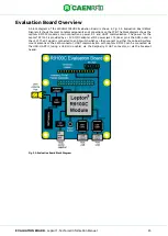
Evaluation Board Default Configuration
In the default configuration of the WRHML37XEVBX evaluation board, the jumpers J1 and J5 should be as
follows:
1.
J1
–
Antenna Selection Jumper
–
should be in the leftmost position so that the external antenna on
connector J2 is selected.
2.
J5
–
series current jumper
–
should be populated (shorted) with a 0 ohm jumper.
3.
SW2 closed so that UART1 interface is accessible via PC USB host via J4.
4.
SW3 closed so that UART2 interface is accessible via PC USB host via J6.
Evaluation Board USB-UART Details
U3 and U4 are USB-UART converters made by Microchip. Their part number is MCP2200-I/MQ. This part
allows a PC to communicate with the Lepton
9
R9100C over USB. The MCP2200 part achieves this by
enumerating as an USB device and adding a COM port. In Windows, this COM ports can be viewed in the
Device Manager under the
“Ports (COM
& LPT)” category. To
identify the COM port associated to UART1
host interface connect USB cable to J4 connector only. To identify the COM port associated to UART2 host
interface connect USB cable to J6 connector only.
Evaluation Board Schematic
The schematic for the WRHML37XEVBX evaluation board is shown in
5.5: Evaluation Board Schematic.
A high resolution PDF of the schematic can be downloaded from the
Lepton
9
R9100C
Technical drawing
).
Fig. 5.5: Evaluation Board Schematic


