caenrfid Lepton9 R9100C Скачать руководство пользователя страница 27


EVALUATION BOARD 

- Lepton

9

 - Technical Information Manual 

27 


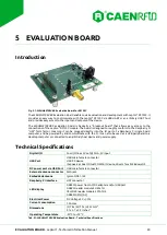
Connector Descriptions 

J4 and J6 are the host USB micro connectors. They allow a PC host to connect to the UART1 and UART2 
communication ports of the Lepton

9

 R9100C module via the USB-UART ICs U3 and U4 respectively. Please 

note that such connectors do not provide power to the board. 

J13 is the power supply connector, the central pin (2.1mm diam.) is the negative terminal. The use of the 
WALIM0000005  Wall  mount  AC-DC  power  supply  is  recommended  (see  §  Development  Kit).  Maximum 
power consumption is 1.5A.  

J1 is the antenna select jumper and its function has been above described.  

J2 is the SMA antenna connector. This port can be connected to any 50 ohm characteristic impedance UHF 
RFID  antenna,  and  with  the  proper  selection  of  the  antenna  selection  jumper  J1,  the  antenna  will  be 
connected to the Lepton

9

 R9100C

s RF port. 

J12 is a coaxial switch connector (Hirose MS-156HF) that can be used to perform measurements directly at 
RF  output  pin  of  Lepton

9

  R9100C.  Verification  of  the  circuit  performance  is  accomplished  by  simply 

inserting the external plug (i.e. Hirose MS-156-HRMJ-H1) in the board mounted receptacle. This action re-
directs the circuit from normal condition to the plug side. Removing the plug restores circuit to its normal 
condition. 

J3  is  a  breakout  header  for  the  IOs  of  the  Lepton

9

  R9100C  as  well  as  a  few  other  signals  on  the  board, 

including  the  power  supplies.  It  can  be  used  to  both  monitor  and  control  the  signals  on  the  board.  If  an 
arbitrary  host  is  to  be  used  to  control  the  Lepton

9

  R9100C,  it  can  be  connected  to  the  UART  Tx  and  Rx 

signals using this header as well as which Raspberry Pi GPIOs will be connected to each signal, when using 

the Raspberry Pi “HAT” head

er J7. 

J7 is the Raspberry Pi 

“HAT” header which a

llows the WRHML37XEVBX evaluation board to be stacked on 

top of a Raspberry Pi single board computer (SBC). It connects power and ground, UART Tx and Rx, as well 
as the other IOs of the Lepton

9

 R9100C.  

J5  is  the  series  curren

t  “IDD”  jumper.  It  al

lows  a  series  current  measurement  to  be  performed  while  the 

Lepton

9

 R9100C is operating. If no series current measurement is desired, the jumper should be populated 

with a short, so that the Lepton

9

 R9100C receives power. 

J9 is the BOOT recovery connector, it has no customer-facing functionality, and can be safely ignored. 

Switch Descriptions 

SW1 is a pushbutton that can be used to reset the Lepton

9

 R9100C. 

SW2  and  SW3  connect  or  disconnect  from  the  USB-UART  IC

s  module’s  UART1  and  UART2  re

spectively 

according to the following configuration: 


SW2 closed to be used when UART1 via USB interface is used (connection to PC via J4 connector) 


SW2 open to be used when UART1 interface is used directly connected to external device (i.e. when 

the  board  is  plugged  in  a  Raspberry  PI  via  HAT  connector  J7  or  it  is  connected  to  external 
controller via the breakout header J3) 


SW3 closed to be used when UART2 via USB interface is used (connection to PC via J6 connector) 


SW3 open to be used when UART2 interface is used directly connected to external device (i.e. when 

the  board  is  plugged  in  a  Raspberry  PI  via  HAT  connector  J7  or  it  is  connected  to  external 
controller via the breakout header J3) 


Fig. 5.4: SW2 and SW3 configuration 


Содержание Lepton9 R9100C

Страница 1: ...TECHNICAL INFORMATION MANUAL Revision 0 22 12 2022 R9100C Lepton9 30dBm 1 Port RAIN RFID Reader Module...

Страница 2: ...er no responsibility is assumed for inaccuracies CAEN RFID reserves the right to modify its products specifications without giving any notice for up to date information please visit www caenrfid com P...

Страница 3: ...Disposal of the product Do not dispose the product in municipal or household waste Please check your local regulations for disposal recycle of electronic products...

Страница 4: ...s 17 EPC Class 1 Generation 2 Operation 18 Supported RF modes 18 4 Layout and Components 19 Introduction 19 PCB Layout for RF 19 50 Ohm Characteristic Impedance 19 Package and Assembly Information 20...

Страница 5: ...L37XEVBX Evaluation Board for R9100C 24 Fig 5 2 Evaluation Board Block Diagram 25 Fig 5 3 WRHML37XEVBX Evaluation Board Key Components 26 Fig 5 4 SW2 and SW3 configuration 27 Fig 5 5 Evaluation Board...

Страница 6: ...j E910 IC that permits to achieve fast reading speed and to be used in dense reader and dense tag environments for top class rated performances The compactness of the device and the surface mount tech...

Страница 7: ...Mod WRHML37XDKEU WRHML37XDKUS is available The kit includes n 1 WRHML37XEVBX Lepton9 R9100C Evaluation Board n 1 Circular Polarized Quadrifilar Antenna SMA ETSI or FCC n 1 Set of Labels n 1 RT0012 Dua...

Страница 8: ...D Reader Module Evaluation Board WRHML37XEVBX Evaluation Board for R1271C R3100C R7100C and R9100C Development Kit WRHML37XDKEU R1271C R3100C R7100C and R9100C ETSI Dev Kit with antenna interface pws...

Страница 9: ...to FCC part 15 247 Standard Compliance EPC C1G2 ISO18000 63 I O Interface 4 I O lines 3 3V level Iout 8mA max Connectivity UART Serial Port Baudrate from 9 6 to 921 6 kbps default 921 6 kbps Databits...

Страница 10: ...enna return loss Impinj RS500 and RS1000 pin to pin compatibility Inventory FastID Tag Population Estimate Select Session Target Access Read Write Lock Kill BlockPermalock and QT Shielded to prevent u...

Страница 11: ...ng paragraphs Fig 3 1 Lepton9 R9100C Example of Block Diagram Required connections VDC_IN and GND are required to power the Lepton9 R9100C RF is required to connect to the UHF RFID antenna UART1 Tx an...

Страница 12: ...internally bypassed and regulated and no external bypass or bulk storage capacitance is required as long as the input voltage is stable If Lepton9 R9100C activity is not required at all times and powe...

Страница 13: ...uld not be applied to the NRST pin This can cause permanent damage to the device GPIO Pins The Lepton9 R9100C s GPIOs can be controlled using the easy2read interface Their drive mode direction and sta...

Страница 14: ...mode after a Sleep wakeup so it should only be pulsed high to wake up the part The WKUP pin operates at a 3 3 V logic level It has a 35 k typical pull down resistor inside the Lepton9 R9100C Voltages...

Страница 15: ...I O 18 GPIO2 Digital I O General purpose I O 19 GPIO3 Digital I O General purpose I O 20 GPIO4 Digital I O General purpose I O 21 STATUS Digital Output R9100C status indication RFU 22 HEALTH Digital O...

Страница 16: ...t power Inventorying tags Idle mode low latency 45 mA Ready to receive easy2read protocol packets Lower latency to return to Active mode Idle mode standard latency 5 mA Ready to receive easy2read pack...

Страница 17: ...25 s WKUP VIL 0 3 0 8 V VIH 2 3 6 V Hysteresis voltage 400 mV Internal pull down resistor 20 35 50 k Digital inputs VIL 0 3 0 8 V VIH 2 3 6 V Hysteresis voltage 400 mV Internal pull down resistor 20 3...

Страница 18: ...FSR Settling time 15 30 sec CLOAD 50 pF RLOAD 5 k Tab 3 8 Analog Interface Specification EPC Class 1 Generation 2 Operation Supported RF modes The Lepton9 R9100C supports the following link profiles w...

Страница 19: ...oefficient will be 10 90 11 1 thus 11 1 of the power will be reflected back into the Lepton9 R9100C and only 88 9 of the power will be transmitted Lepton9 R9100C is designed to connect to a 50 Ohm cha...

Страница 20: ...ls designed to assist in designing PCB transmission lines with the correct characteristic impedances For example the TXLine tool from National Instruments is very useful for performing these calculati...

Страница 21: ...MPONENTS Lepton9 Technical Information Manual 21 PCB Footprint Recommended footprint copper and pastemask dimensions are shown in the following Fig 4 3 Recommended Etched Copper Footprint All Pads Fig...

Страница 22: ...NTS Lepton9 Technical Information Manual 22 SMT Reflow Information The solder manufacturer s recommended reflow profile is shown in the following figure Fig 4 5 Recommended Solder Reflow Profile for t...

Страница 23: ...if the HIC is 10 when read at 23 C 5 C 4 After MBB is opened devices should go through reflow for board assembly within 168 hours at factory conditions of 30 C 60 RH or stored at 10 RH If both conditi...

Страница 24: ...le board computer and be powered by and communicate with the Pi It can also be used as a USB peripheral to a desktop computer or connected to an arbitrary host device and power supply Technical Specif...

Страница 25: ...in connections power RF and UART communication The power for the Lepton9 R9100C is provided by a 5V AC DC adapter at DC power jack J13 inner pin is the GND outer is the 5V The RF signal is connected t...

Страница 26: ...oving the jumper causes the switch to connect the Lepton9 R9100C s RF port to the SMT antenna A1 Installing the jumper in the leftmost position selects the SMA connector J1 Installing the jumper in th...

Страница 27: ...is to be used to control the Lepton9 R9100C it can be connected to the UART Tx and Rx signals using this header as well as which Raspberry Pi GPIOs will be connected to each signal when using the Rasp...

Страница 28: ...UART converters made by Microchip Their part number is MCP2200 I MQ This part allows a PC to communicate with the Lepton9 R9100C over USB The MCP2200 part achieves this by enumerating as an USB devic...

Страница 29: ...n Board Front and Backside flipped Layout The ground plane free of component on the bottom side of the board under Lepton9 module as shown in detail in the following figure is recommended in order to...

Страница 30: ...Lepton9 R9100C over USB The MCP2200 part achieves this by enumerating as an USB device and adding a COM port In Windows this COM ports can be viewed in the Device Manager under the Ports COM LPT categ...

Страница 31: ...o the module via Easy Controller software the serial settings shall be added to the COM port address since Lepton9 R9100C module has a different baudrate 921600bps from default value used by the SW 4...

Страница 32: ...der click on Start Inventory and see tags information displayed on the main window For more information on the CAEN RFID Easy Controller for Windows application usage please refer to the relevant user...

Страница 33: ...EGULATORY COMPLIANCE RoHS Directive The Lepton9 R9100C RFID Reader is compliant with the EU Directive 2015 863 EU RoHS3 and the UK Regulation 2012 SI 2012 3032 RoHS on the Restriction of the Use of ce...

Отзывы: