Cabletron Systems MMAC-Plus 9T125-24 Скачать руководство пользователя страница 4


Notice

ii


FCC Notice


This device complies with Part 15 of the FCC rules. Operation is subject to the following two 
conditions: (1) this device may not cause harmful interference, and (2) this device must accept any 
interference received, including interference that may cause undesired operation.


NOTE:


 This equipment has been tested and found to comply with the limits for a Class A digital 

device, pursuant to Part 15 of the FCC rules. These limits are designed to provide reasonable 
protection against harmful interference when the equipment is operated in a commercial environment. 
This equipment uses, generates, and can radiate radio frequency energy and if not installed in 
accordance with the operator’s manual, may cause harmful interference to radio communications. 
Operation of this equipment in a residential area is likely to cause interference in which case the user 
will be required to correct the interference at his own expense.


WARNING:


 Changes or modifications made to this device which are not expressly approved by the 

party responsible for compliance could void the user’s authority to operate the equipment.


VCCI Notice


This is a Class A product based on the standard of the Voluntary Control Council for Interference by 
Information Technology Equipment (VCCI). If this equipment is used in a domestic environment, 
radio disturbance may arise. When such trouble occurs, the user may be required to take corrective 
actions.


DOC Notice


This digital apparatus does not exceed the Class A limits for radio noise emissions from digital 
apparatus set out in the Radio Interference Regulations of the Canadian Department of 
Communications.

Le présent appareil numérique n’émet pas de bruits radioélectriques dépassant les limites applicables 
aux appareils numériques de la class A prescrites dans le Règlement sur le brouillage radioélectrique 
édicté par le ministère des Communications du Canada.

Содержание MMAC-Plus 9T125-24

Страница 1: ...9032053 01 SmartSwitch 9000 9T125 24 User s Guide...

Страница 2: ......

Страница 3: ...AMAGES WHATSOEVER INCLUDING BUT NOT LIMITED TO LOST PROFITS ARISING OUT OF OR RELATED TO THIS MANUAL OR THE INFORMATION CONTAINED IN IT EVEN IF CABLETRON SYSTEMS HAS BEEN ADVISED OF KNOWN OR SHOULD HA...

Страница 4: ...in which case the user will be required to correct the interference at his own expense WARNING Changes or modifications made to this device which are not expressly approved by the party responsible fo...

Страница 5: ...Equipment for use in a Commercial or Light Industrial Environment We the undersigned hereby declare under our sole responsibility that the equipment packaged with this notice conforms to the above di...

Страница 6: ...Notice iv...

Страница 7: ...4 The Reset Switch 2 6 Chapter 3 Operation Bridging 3 1 Transparent Bridging 3 2 Source Route Bridging 3 2 Spanning Tree Algorithm 3 3 Flexible Network Bus FNB 3 3 System Management Buses 3 4 SMB 1 B...

Страница 8: ...Contents vi...

Страница 9: ...re System Management Interfaces to the two System Management Buses SMB 1 and SMB 10 for intermodule management Connectivity The 9T125 24 provides twenty four RJ45 Trunk Coupling Unit TCU lobe connecto...

Страница 10: ...Introduction 1 2 Figure 1 1 The 9T125 24 Module MicroLAN Module 1 2 1 2 3 4 5 6 7 8 9 10 11 12 13 14 15 16 17 18 19 20 21 22 23 24 16 Mb SMB CPU FNB 9T125 24 TOKEN RING...

Страница 11: ...ng LANVIEW LEDs The 9T125 24 Module uses LANVIEW the Cabletron Systems built in visual diagnostic and status monitoring system With LANVIEW LEDs you can quickly identify the device port and physical l...

Страница 12: ...he unit etc The serial and revision numbers of all involved Cabletron Systems products in the network A description of your network environment layout cable type etc Network load and frame size at the...

Страница 13: ...the module from the shipping box Save the box and packing materials in the event the module must be reshipped 2 Remove the module from the plastic bag Observe all precautions to prevent damage from El...

Страница 14: ...These consist of an eight position dip switch explained in the next section replaceable PROMs and sockets for RAM These will be used for future upgrades Figure 2 1 User Accessible Components SMB 1 PR...

Страница 15: ...e factory defaults toggle this switch Once reset you can use the defaults or enter new parameters which are stored in NVRAM when the module is powered down and remain there until the switch is toggled...

Страница 16: ...be reshipped 4 Attach one end of the ESD wrist strap packaged with the SmartSwitch 9000 chassis to your wrist Plug the other end into the ESD Wrist Strap Grounding receptacle in the lower right corne...

Страница 17: ...he MicroLAN Module Metal Back Panel Module Guides Module Jack for ESD Wrist Strap Plastic Tab Warning Ensure that the circuit card is between the card guides Lock down the top and bottom plastic tabs...

Страница 18: ...eset switch twice within three seconds causes the processor i960 to reset Pressing and holding the switch on for three or more seconds causes the module to shutdown Pressing and holding the switch aga...

Страница 19: ...cur between these two rings and or to any other SmartSwitch 9000 module via the Flexible Network Bus Figure 3 1 9T125 24 Block Diagram Bridging The 9T125 24 is configured for SRT bridging It will pass...

Страница 20: ...the destination address of each subsequent packet that travels to the bridge If the destination address of a packet resides on the bridge segment the 9T125 24 does not forward across the Token Ring l...

Страница 21: ...hin the network The bridges then apply the Spanning Tree Algorithm STA to select a root bridge and then determine primary data paths within potential data loop configurations Spanning Tree Algorithm i...

Страница 22: ...ional Ethernet Port Interface Module EPIM located on the front of the Environmental Module Through an EPIM connection full SNMP management of the SmartSwitch 9000 is available out of band from user da...

Страница 23: ...ideal for networks designed to switching multiple lower speed LANs to FDDI and or networks designed using an FDDI collapsed backbone i960 Core The i960 core in the FNB module serves two major function...

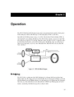
Страница 24: ...Operation 3 6...

Страница 25: ...status of the module and may be used as an aid in troubleshooting Figure 4 1 LANVIEW LEDs 1 2 1 2 3 4 5 16 Mb SMB CPU FNB 9T122 24 TOKEN RING SMB CPU FNB 9T125 24 TOKEN RING System Status FNB Transmi...

Страница 26: ...d Not fully operational i e one bad port Yellow Green Booting Blinks yellow and green while booting Red Reset Normal power up reset Red Flashing Failed Fatal error has occurred Off Power off Module po...

Страница 27: ...y Port enabled Yellow Flashing Link Activity Flashing rate indicates rate of activity Off No link No activity Table 4 5 Token Ring Transmit LEDs LED Color State Red Flashing Fault Ring is Beaconing Gr...

Страница 28: ...LANVIEW LEDs 4 4...

Страница 29: ...A EN 55022 Class A VCCI Class I EMC requirements of EN 50082 1 IEC 801 2 ESD IEC 801 3 Radiated susceptibility IEC 801 4 EFT Service MTBF MHBK 217E 200 000 hrs MTTR 0 5 hr It is the responsibility of...

Страница 30: ...x 17 4 H x 1 2 W inches Weight Unit 1 36 kg 3 lb Shipping 1 81 kg 4 lb Electrical CPU i960 Shared DRAM Memory 12Mb expandable to 32Mb Local DRAM Memory 16Mb expandable to 32Mb Flash 4Mb expandable to...

Отзывы: