Cabletron Systems MMAC-Plus 9T125-24 Скачать руководство пользователя страница 12


Introduction

1-4


Related Manuals


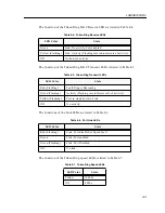
The manuals listed below should be used to supplement the procedures and 
technical data contained in this manual.

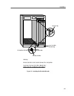
SmartSwitch 9000 Installation Guide

SmartSwitch 9000 Operations Guide 

SmartSwitch 9000 9C300-1 Environmental Module User’s Guide

SmartSwitch 9000 9C214-1 AC Power Supply User’s Guide

SmartSwitch 9000 Local Management User’s Guide


Getting Help


For additional support related to this device or document, contact the Cabletron Systems Global Call 
Center:

Before calling the Cabletron Systems Global Call Center, have the following information ready:

Your Cabletron Systems service contract number 

A description of the failure

A description of any action(s) already taken to resolve the problem (e.g., changing mode switches, 
rebooting the unit, etc.)

The serial and revision numbers of all involved Cabletron Systems products in the network

A description of your network environment (layout, cable type, etc.)

Network load and frame size at the time of trouble (if known)

The device history (i.e., have you returned the device before, is this a recurring problem, etc.)

Any previous Return Material Authorization (RMA) numbers


Phone

(603) 332-9400

Internet mail

[email protected]

FTP

ctron.com (134.141.197.25)

Login 


anonymous


Password 


your email address


BBS

(603) 335-3358 

Modem setting

8N1: 8 data bits, No parity, 1 stop bit

For additional information about Cabletron Systems or its products, visit the 
World Wide Web site:


http://www.cabletron.com/ 


For technical support, select


Service and Support


.

To send comments or suggestions concerning this document, contact the 
Cabletron Systems Technical Writing Department via the following 
email address:


[email protected]


Make sure to include the document Part Number in the email message.

Содержание MMAC-Plus 9T125-24

Страница 1: ...9032053 01 SmartSwitch 9000 9T125 24 User s Guide...

Страница 2: ......

Страница 3: ...AMAGES WHATSOEVER INCLUDING BUT NOT LIMITED TO LOST PROFITS ARISING OUT OF OR RELATED TO THIS MANUAL OR THE INFORMATION CONTAINED IN IT EVEN IF CABLETRON SYSTEMS HAS BEEN ADVISED OF KNOWN OR SHOULD HA...

Страница 4: ...in which case the user will be required to correct the interference at his own expense WARNING Changes or modifications made to this device which are not expressly approved by the party responsible fo...

Страница 5: ...Equipment for use in a Commercial or Light Industrial Environment We the undersigned hereby declare under our sole responsibility that the equipment packaged with this notice conforms to the above di...

Страница 6: ...Notice iv...

Страница 7: ...4 The Reset Switch 2 6 Chapter 3 Operation Bridging 3 1 Transparent Bridging 3 2 Source Route Bridging 3 2 Spanning Tree Algorithm 3 3 Flexible Network Bus FNB 3 3 System Management Buses 3 4 SMB 1 B...

Страница 8: ...Contents vi...

Страница 9: ...re System Management Interfaces to the two System Management Buses SMB 1 and SMB 10 for intermodule management Connectivity The 9T125 24 provides twenty four RJ45 Trunk Coupling Unit TCU lobe connecto...

Страница 10: ...Introduction 1 2 Figure 1 1 The 9T125 24 Module MicroLAN Module 1 2 1 2 3 4 5 6 7 8 9 10 11 12 13 14 15 16 17 18 19 20 21 22 23 24 16 Mb SMB CPU FNB 9T125 24 TOKEN RING...

Страница 11: ...ng LANVIEW LEDs The 9T125 24 Module uses LANVIEW the Cabletron Systems built in visual diagnostic and status monitoring system With LANVIEW LEDs you can quickly identify the device port and physical l...

Страница 12: ...he unit etc The serial and revision numbers of all involved Cabletron Systems products in the network A description of your network environment layout cable type etc Network load and frame size at the...

Страница 13: ...the module from the shipping box Save the box and packing materials in the event the module must be reshipped 2 Remove the module from the plastic bag Observe all precautions to prevent damage from El...

Страница 14: ...These consist of an eight position dip switch explained in the next section replaceable PROMs and sockets for RAM These will be used for future upgrades Figure 2 1 User Accessible Components SMB 1 PR...

Страница 15: ...e factory defaults toggle this switch Once reset you can use the defaults or enter new parameters which are stored in NVRAM when the module is powered down and remain there until the switch is toggled...

Страница 16: ...be reshipped 4 Attach one end of the ESD wrist strap packaged with the SmartSwitch 9000 chassis to your wrist Plug the other end into the ESD Wrist Strap Grounding receptacle in the lower right corne...

Страница 17: ...he MicroLAN Module Metal Back Panel Module Guides Module Jack for ESD Wrist Strap Plastic Tab Warning Ensure that the circuit card is between the card guides Lock down the top and bottom plastic tabs...

Страница 18: ...eset switch twice within three seconds causes the processor i960 to reset Pressing and holding the switch on for three or more seconds causes the module to shutdown Pressing and holding the switch aga...

Страница 19: ...cur between these two rings and or to any other SmartSwitch 9000 module via the Flexible Network Bus Figure 3 1 9T125 24 Block Diagram Bridging The 9T125 24 is configured for SRT bridging It will pass...

Страница 20: ...the destination address of each subsequent packet that travels to the bridge If the destination address of a packet resides on the bridge segment the 9T125 24 does not forward across the Token Ring l...

Страница 21: ...hin the network The bridges then apply the Spanning Tree Algorithm STA to select a root bridge and then determine primary data paths within potential data loop configurations Spanning Tree Algorithm i...

Страница 22: ...ional Ethernet Port Interface Module EPIM located on the front of the Environmental Module Through an EPIM connection full SNMP management of the SmartSwitch 9000 is available out of band from user da...

Страница 23: ...ideal for networks designed to switching multiple lower speed LANs to FDDI and or networks designed using an FDDI collapsed backbone i960 Core The i960 core in the FNB module serves two major function...

Страница 24: ...Operation 3 6...

Страница 25: ...status of the module and may be used as an aid in troubleshooting Figure 4 1 LANVIEW LEDs 1 2 1 2 3 4 5 16 Mb SMB CPU FNB 9T122 24 TOKEN RING SMB CPU FNB 9T125 24 TOKEN RING System Status FNB Transmi...

Страница 26: ...d Not fully operational i e one bad port Yellow Green Booting Blinks yellow and green while booting Red Reset Normal power up reset Red Flashing Failed Fatal error has occurred Off Power off Module po...

Страница 27: ...y Port enabled Yellow Flashing Link Activity Flashing rate indicates rate of activity Off No link No activity Table 4 5 Token Ring Transmit LEDs LED Color State Red Flashing Fault Ring is Beaconing Gr...

Страница 28: ...LANVIEW LEDs 4 4...

Страница 29: ...A EN 55022 Class A VCCI Class I EMC requirements of EN 50082 1 IEC 801 2 ESD IEC 801 3 Radiated susceptibility IEC 801 4 EFT Service MTBF MHBK 217E 200 000 hrs MTTR 0 5 hr It is the responsibility of...

Страница 30: ...x 17 4 H x 1 2 W inches Weight Unit 1 36 kg 3 lb Shipping 1 81 kg 4 lb Electrical CPU i960 Shared DRAM Memory 12Mb expandable to 32Mb Local DRAM Memory 16Mb expandable to 32Mb Flash 4Mb expandable to...

Отзывы: