


Chapter 4: Connecting to the Network
Page 4-6
MicroMMAC Installation Guide
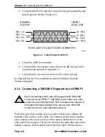
b. Verify that the RJ45 connector on the twisted pair segment has the
proper pinouts. Refer to Figure 4-4.
Figure 4-4
Cable Pinouts RJ45 Port
c.
Check the cable for continuity.
d. Check that the twisted pair connection meets dB loss and cable
specifications outlined in Appendix C.
e.
Check that the crossover switch is in the correct position.
If a link still has not been established, contact Cabletron Systems
Technical Support.
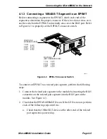
4.1.4 Connecting a 10BASE-F Segment to an EPIM-F1
Each fiber optic link consists of two strands of fiber optic cabling: the
transmit (TX) and the receive (RX). The transmit strand from a module
port connects to the receive port of a fiber optic Ethernet device at the
other end of the segment. The receive strand of the applicable port on the
module connects to the transmit port of the fiber optic Ethernet device.
!
C AUT IO N
When connecting a fiber optic link segment with SMA 906
connectors to an EPIM-F1 with SMA ports, make sure each
connector uses half alignment, NOT full alignment, sleeves. A
full alignment sleeve damages the receive port. SMA 905
connectors do not need alignment sleeves.
Tx+ PIN 1
Tx- PIN 2
Rx- PIN 3
Rx+ PIN 6
MicroMMAC
RJ45 PORT
PIN 1 Tx+
PIN 2 Tx-
PIN 3 Rx-
PIN 4 Rx+
10BASE-T
DEVICE PORT
RX+/RX- AND TX+/TX- MUST SHARE A COMMON PAIR.
090833


