background image

Configuring Your ELS10-26

3-13

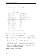
 • Perturbed — Trunking is enabled, and a good trunk connection 

has been established. However, the forwarding of data packets 
is temporarily suspended to allow for a change in the 
membership of the Trunk Group.

3.8  ENABLING PORT MONITORING

The ELS10-26 allows you to monitor the 10BASE-T ports on the 
ELS10-26 (you cannot monitor the 100BASE ports ). The 
monitoring of network traffic is performed by the ELS10-26 
hardware, and the monitor image reflects the original packet. The 
ELS10-26 monitoring function maintains the original packet 
ordering of bridging frames between the inbound and outbound 
interfaces. 

Using the LCM or a NMS, you can monitor a port, and select to 
monitor only packets received, only packets transmitted, or 
packets both received and transmitted by a port (if the port is 
operating in half duplex). In full duplex you can mirror either 
recieved packet or transmitted packet (not both).

To enable port monitoring on the ELS10-26:

1. Connect a network analyzer to the port labeled MONX on the 

ELS10-26.

2. Using the LCM or NMS, select the port or range of ports you 

want to monitor. Also select to monitor the received packets 
(Rx) or transmitted packets (Tx). If you do not select either the 
transmit or recieve options, the ELS10-26 will monitor both 
types of packets. 

For example, 

mirror 2 Tx

This will turn on monitoring for packets transmitted on port 2. 

Содержание ELS10-26TX

Страница 1: ...20X 22X 24X MONX 26X 27 LINK STATUS LINK STATUS 26 27 LINK STATUS LINK STATUS LINK STATUS LINK STATUS LINK STATUS LINK STATUS 13 14 15 16 23 24 21 22 17 18 19 20 LINK STATUS LINK STATUS LINK STATUS LI...

Страница 2: ......

Страница 3: ...manual may be trademarks or registered trademarks of their respective companies FCC NOTICE This device complies with Part 15 of the FCC rules Operation is subject to the following two conditions 1 th...

Страница 4: ...n a domestic environment radio disturbance may arise When such trouble occurs the user may be required to take corrective actions CABLETRON SYSTEMS INC PROGRAM LICENSE AGREEMENT IMPORTANT Before utili...

Страница 5: ...SHALL CABLETRON OR ITS SUPPLIERS BE LIABLE FOR ANY DAMAGES WHATSOEVER INCLUDING WITHOUT LIMITATION DAMAGES FOR LOSS OF BUSINESS PROFITS BUSINESS INTERRUPTION LOSS OF BUSINESS INFORMATION SPECIAL INCI...

Страница 6: ...1 EN 60950 Equipment Type Environment Networking Equipment for use in a Commercial or Light Industrial Environment We the undersigned hereby declare under our sole responsibility that the equipment p...

Страница 7: ...FEPIM 2 4 2 3 INSTALLING THE ELS10 26 2 5 2 4 CHECKING THE POWER UP DIAGNOSTICS SEQUENCE 2 8 2 5 CONNECTING THE LOCAL CONSOLE MANAGER 2 9 2 6 CONNECTING TO THE NETWORK 2 9 2 6 1 Connecting UTP Cables...

Страница 8: ...G YOUR ELS10 26 4 1 ELS10 26 MANAGEMENT TOOLS 4 1 4 2 ELS10 26 STATISTICS 4 1 4 2 1 Gathering Statistics 4 2 4 2 2 System Statistics 4 2 4 2 3 Ethernet Port Statistics 4 3 4 3 USING LCM TO CHECK ELS10...

Страница 9: ...5 3 5 3 STATUS AND ACTIVITY INDICATORS 5 3 5 4 TROUBLESHOOTING 5 6 5 5 ELS10 26 DOES NOT POWER UP 5 6 5 5 1 Connectivity Problems 5 6 5 5 2 ELS10 26 Has Rebooted 5 6 5 5 3 ELS10 26 Does Not Respond to...

Страница 10: ...viii Contents...

Страница 11: ...Chapter 1 Introduction outlines the contents of this manual and provides an overview of the SmartSTACK 10 ELS10 26 s switching functions applications and the Local Console Manager LCM Chapter 2 Unpac...

Страница 12: ...ssary provides a glossary of terms both specific to the SmartSTACK 10 ELS10 26 and common to the networking field 1 2 GETTING HELP If you need additional support related to the SmartSTACK 10 ELS10 26...

Страница 13: ...The device history i e have you returned the device before is this a recurring problem etc Any previous Return Material Authorization RMA numbers For additional information about Cabletron Systems pr...

Страница 14: ...ains enterprise MIB information Interconnections Bridges and Routers Radia Perlman Addison Wesley 1992 Internetworking with TCP IP Principles Protocols and Architecture 2nd edition Volumes I and II Do...

Страница 15: ...STACK 10 ELS10 26 Provides dedicated bandwidth for each network connected to its ports Provides full store and forward bridging functionality Provides complete error checking functionality Provides po...

Страница 16: ...arate broadcast domains Compilation of statistics by port for traffic generated by each user device connected to a SmartSTACK 10 ELS10 26 segment 1 5 1 SmartSTACK 10 ELS10 26 Architecture The SmartSTA...

Страница 17: ...not process any Network Layer information it provides a high level of performance in terms of packet throughput In addition the SmartSTACK 10 ELS10 26 does not need to learn network topology requiring...

Страница 18: ...as the originating packet the SmartSTACK 10 ELS10 26 forwards the packet to the network segment associated with that destination address if known However if the packet s source and destination address...

Страница 19: ...ing Tree compliant bridges in the network dynamically configure the network topology into a single Spanning Tree by exchanging Bridge Protocol Data Units BPDUs Typically each LAN segment is sent one B...

Страница 20: ...tional When devices are added to the network removed from it or relocated you do not have to reconfigure the SmartSTACK 10 ELS10 26 The unit automatically learns new device addresses recognizes when a...

Страница 21: ...mirroring Local port mirroring is when the diagnostic port is on the same SmartSTACK 10 ELS10 26 as the mirrored port The mirrored port has to be local to the SmartSTACK 10 ELS10 26 Packet Capturing a...

Страница 22: ...SmartSTACK 10 ELS10 26 Trunking with 10 Mbps Ports ELS10 26TX STATUS PORT STATUS MODE 10BASE T 100BASE TX FEPIM 2X 4X 6X 8X 10X 12X 14X 16X 18X 20X 22X 24X MONX 26X 27 LINK STATUS LINK STATUS 26 27 L...

Страница 23: ...TATUS LINK STATUS 26 27 LINK STATUS LINK STATUS LINK STATUS LINK STATUS LINK STATUS LINK STATUS 13 14 15 16 23 24 21 22 17 18 19 20 LINK STATUS LINK STATUS LINK STATUS LINK STATUS LINK STATUS LINK STA...

Страница 24: ...US LINK STATUS LINK STATUS LINK STATUS LINK STATUS LINK STATUS 3 4 1 2 7 8 5 6 11 12 9 10 TX ACT FDX MON RX COL 100 USR PWR CPU RESET 25 MON COM ELS10 26TX STATUS PORT STATUS MODE 10BASE T 100BASE TX...

Страница 25: ...the network to find specific host addresses ELS10 26TX STATUS PORT STATUS MODE 10BASE T 100BASE TX FEPIM 2X 4X 6X 8X 10X 12X 14X 16X 18X 20X 22X 24X MONX 26X 27 LINK STATUS LINK STATUS 26 27 LINK STA...

Страница 26: ...rnet segments A and B that do not include a SmartSTACK 10 ELS10 26 Figure 1 8 Multiple Ethernet Segments Sharing 10 Mbps Bandwidth Each host on segments A and B is limited to sharing a network bandwid...

Страница 27: ...of a workgroup will receive and transmit packets from any ports However if you configure the SmartSTACK 10 ELS10 26 with workgroup A and B as shown in Figure 1 9 broadcast traffic from workgroup A por...

Страница 28: ...s Network Management System or a standard SNMP based Network Management System to manage the SmartSTACK 10 ELS10 26 For a list of available SmartSTACK 10 ELS10 26 network management tools see Section...

Страница 29: ...error message A previous command can be repeated by typing MAC addresses are displayed in little endian Ethernet least significant bit bit order with each octet separated by a colon For example ELS10...

Страница 30: ...an ASCII terminal or terminal emulator See Section 2 5 Connecting the Local Console Manager for instructions When you want to use LCM begin by pressing the Enter key several times to get the LCM promp...

Страница 31: ...o disable a set of ports community to change the password community name sttimer TIME VALUE to set or display st age timer workgroup NAME delete PORT RANGE INFO to set or display workgroups speed PORT...

Страница 32: ...lays the traps messages captured by the SmartSTACK 10 ELS10 26 The following is an example of a traplog display ELS10 26TX traplog Trap 16 0 00 00 The unit has booted Trap 25 0 00 00 The unit s spanni...

Страница 33: ...on to this manual the Getting Started with the SmartSTACK 10 ELS10 26 guide the ELS10 26 MIB Reference Guide and Release Notes are also included 2 1 ELS10 26 FRONT PANEL The ELS10 26 provides 25 10BAS...

Страница 34: ...TUS 26 27 LINK STATUS LINK STATUS LINK STATUS LINK STATUS LINK STATUS LINK STATUS 13 14 15 16 23 24 21 22 17 18 19 20 LINK STATUS LINK STATUS LINK STATUS LINK STATUS LINK STATUS LINK STATUS 3 4 1 2 7...

Страница 35: ...cates the port is copying to the monitor port On Indicates that errored packets were received Link Individual Ports On Indicates the link is good Off Indicates there is no link Status Individual Ports...

Страница 36: ...Install the FEPIM as shown in Figure 2 2 Ensure that the rear connector is seated firmly before tightening the three mounting screws 5 Replace the plate and two screws on the side of the FEPIM slot 6...

Страница 37: ...Unpacking and Installing Your ELS10 26 2 5 Figure 2 2 Installing an FEPIM 1742 39 FE 100TX 10 100 16 15 Standoff Standoffs Module Motherboard Connector Module Connector Faceplate...

Страница 38: ...emperature make sure the rack environment temperature is within the Operating Temperature range specified in Appendix A Air Flow Make sure there is at least 2 inches or more on both sides of the ELS10...

Страница 39: ...T STATUS MODE 10BASE T 100BASE TX FEPIM 2X 4X 6X 8X 10X 12X 14X 16X 18X 20X 22X 24X MONX 26X 27 LINK STATUS LINK STATUS 26 27 LINK STATUS LINK STATUS LINK STATUS LINK STATUS LINK STATUS LINK STATUS 13...

Страница 40: ...wer up the ELS10 26 the following occurs 1 All LEDs except the Port Link LEDs turn on for one second 2 The Power Pwr LED remains on 3 The CPU LED starts flashing 4 After several seconds the Port Link...

Страница 41: ...several times If the ELS10 26 and terminal are operational LCM responds with the ELS10 26 prompt 4 LCM is now ready to use Refer to Section 1 6 Local Console Manager for a general overview of LCM and...

Страница 42: ...S10 26 Twisted Pair Connection 3 Verify that a Link exists by checking that the port LINK LED is on solid green If the LINK LED is off perform the following steps until it is on Caution To establish a...

Страница 43: ...details 4 Repeat step 2 above until all connections have been made 2 6 2 Connecting a UTP Segment to the FE 100TX An FE 100 TX installed in port slot 27 is often used to provide a connection between t...

Страница 44: ...to the segment and is powered ON 2 Connect the twisted pair segment to the module by inserting the RJ45 connector on the twisted pair segment into the RJ45 port on the module See Figure 2 7 3 Verify...

Страница 45: ...SC style network port see Figure 2 8 Cabletron Systems supplies fiber optic cable that uses SC style connectors that are keyed to ensure proper crossing over of the transmit and receive fibers Fiber...

Страница 46: ...that the port LINK LED is solid green If the LINK LED is off perform the following steps until it is on a Check that the power is turned on for the device at the other end of the Link Caution Do not...

Страница 47: ...nd of the fiber optic link segment c Verify that the fiber connection meets the dB loss specifications If a Link has not been established contact Cabletron Systems Global Call Center Refer to Section...

Страница 48: ...2 16 Unpacking and Installing Your ELS10 26...

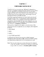
Страница 49: ...o configure and manage the ELS10 26 through the out of band RS232C connection attached to any non intelligent terminal or a PC emulating a non intelligent terminal See Section 3 1 Assigning IP Address...

Страница 50: ...for each port must be unique IP addresses are divided into classes based on what portion of the address is network or port information The address classes are A B and C Class A addresses are used in...

Страница 51: ...es are used for small networks The first three bytes identify the network and the last byte identifies the port The first byte of a class C address must be in the range 192 223 The address 192 138 217...

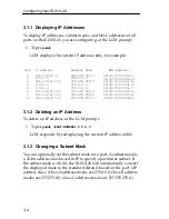
Страница 52: ...address mask used in IP to specify a particular subnet If the subnet mask is 0 0 0 0 the ELS10 26 will automatically convert the displayed mask to the standard default based on the port s IP address c...

Страница 53: ...ns include off on the default with BPDU enabled noBPDU BPDU Bridge Protocol Data Unit is a data unit transmitted as part of the IEEE 802 1d Spanning Tree protocol The exchange of BPDUs allows bridges...

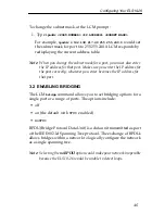
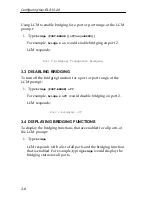
Страница 54: ...t or port range at the LCM prompt 1 Type bridge PORT RANGE off For example bridge 2 off would disable bridging on port 2 LCM responds 3 4 DISPLAYING BRIDGING FUNCTIONS To display the bridging function...

Страница 55: ...tension to the 802 1D Spanning Tree algorithm It enables you to use multiple 10BASE T Ethernet segments to connect ELS10 26s together while maintaining first in first out ordering of Ethernet packets...

Страница 56: ...14X 16X 18X 20X 22X 24X MONX 26X 27 LINK STATUS LINK STATUS 26 27 LINK STATUS LINK STATUS LINK STATUS LINK STATUS LINK STATUS LINK STATUS 13 14 15 16 23 24 21 22 17 18 19 20 LINK STATUS LINK STATUS L...

Страница 57: ...STATUS LINK STATUS LINK STATUS LINK STATUS LINK STATUS LINK STATUS 3 4 1 2 7 8 5 6 11 12 9 10 TX ACT FDX MON RX COL 100 USR PWR CPU RESET 25 MON COM ELS10 26TX STATUS PORT STATUS MODE 10BASE T 100BAS...

Страница 58: ...ELS10 26 ports are to become forwarding ports As ports within a Trunk Group become forwarding ports traffic within the Trunk Group is momentarily halted to guarantee the first in first out ordering of...

Страница 59: ...Addresses are not required for trunking to function To check the status for ports configured for trunking at the LCM prompt 1 Type status PORT RANGE ELS10 26 trunk 2 4 Port 2 trunking joined to Bridge...

Страница 60: ...automatically initiated to establish a good trunk connection Joined Trunking is enabled and the Trunking Protocol has established a good trunk connection Off Trunking is not enabled Port 1 Status ELS...

Страница 61: ...een the inbound and outbound interfaces Using the LCM or a NMS you can monitor a port and select to monitor only packets received only packets transmitted or packets both received and transmitted by a...

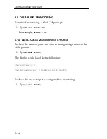
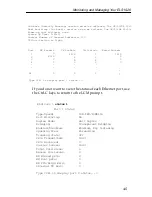
Страница 62: ...le mirror 2 off 3 10 DISPLAYING MONITORING STATUS To check the status of your current monitoring configuration at the LCM prompt 1 Type mirror PORT The display could look like the following To check t...

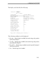
Страница 63: ...s enabled monitoring both transmit and receive packets No Monitoring is not enabled Port 1 Status ELS10 26 status 1 Type Speed 10B TPX 10Mbits Port Mirroring No Duplex Mode Half Duplex Bridging Transp...

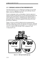
Страница 64: ...Figure 3 3 shows an ELS10 26 that has been programmed to identify workgroups A and B Workgroup A uses ports 3 through 5 13 and 16 and workgroup B uses ports 7 11 16 and 24 Port 16 connects a segment t...

Страница 65: ...splay Name b Ports 7 11 16 24 Info all Port 16 has been assigned to a segment that includes ports that belong to workgroup A and workgroup B Port 13 connects workgroup A to the router and port 24 conn...

Страница 66: ...To display the network classification of a specific workgroup at the LCM prompt 1 Type workgroup NAME INFO 3 12 ASSIGNING A COMMUNITY NAME A community name is similar to a password You use the same s...

Страница 67: ...y configured for automatic multicast storm protection You define what level of multicasts the ELS10 26 will recognize as a multicast storm by specifying the number of multicast packets that can be tra...

Страница 68: ...nfiguration options You may need to modify your configuration using an NMS This section provides several common MIB variables you may want to change Refer to the ELS10 26 MIB Reference Guide for a com...

Страница 69: ...entifies the physical location of the ELS10 26 sysLocation system 6 DisplayString SIZE 0 255 3 16 2 Community Names The set community name variable from the Cabletron proprietary MIB must be initializ...

Страница 70: ...learned addresses are automatically deleted from the ELS10 26 Bridge Address Table after a certain length of time The aging time default is five minutes as set by the IEEE 802 1d standard However you...

Страница 71: ...te for your Local Console Manager LCM connection 4 1 ELS10 26 MANAGEMENT TOOLS LCM is a command line interface built into the ELS10 26 that enables you to monitor and manage the ELS10 26 through the o...

Страница 72: ...e to a possible malfunction 4 2 1 Gathering Statistics For purposes of network management managed objects must be identified Creation of a managed object is achieved by placing its identifier and a se...

Страница 73: ...oth network activity and utilization and in some cases indicate faulty equipment or cabling The number of non unicast multicast and broadcast and unicast packets received from the port The following s...

Страница 74: ...bed in the sections that follow 4 3 1 Displaying Status The status command displays the status of the ELS10 26 and automatically pages through the status of all of the Ethernet ports pausing at each s...

Страница 75: ...CPU utilization is light Port RX Packets TX Packets Collisions Erred Packets 1 2 3 4 0 6978 0 0 1676 8 0 0 1676 0 0 0 0 0 0 0 24 0 0 0 0 Type CR to display port 1 status Port 1 Status ELS10 26 status...

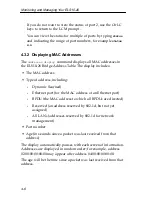
Страница 76: ...address Type of address including Dynamic learned Ethernet port for the MAC address of an Ethernet port BPDU the MAC address to which all BPDUs are directed Reserved an address reserved by 802 1d but...

Страница 77: ...4 06 03 2a 43 LCM would display the following information You can display a range of addresses by using a net mask This is helpful when determining the status associated with stations containing the s...

Страница 78: ...rames To 02 04 06 03 2a 43 02 04 06 00 2a 67 02 04 06 a3 70 2b Learned Learned Learned 5 4 6 21 1 0 1181 3421 15339 73 0 235 Enter CR to continue Ctrl C to exit IP Address Address Mask MAC Address 1 2...

Страница 79: ...te of your terminal connection Setting a reboot time You can use the Local Console Manager LCM any of the Cabletron Systems NMSs or a standard SNMP based NMS to manage the ELS10 26 Refer to Section 4...

Страница 80: ...esponds Once an Ethernet port is disabled it will be disabled until you enable it again Resetting the ELS10 26 will not enable a port that has been disabled 4 5 2 Enabling a Port When you enable an Et...

Страница 81: ...work devices that do not support RIP 4 5 3 Changing a Subnet Mask You can optionally set the subnet mask for a port A subnet mask is a 32 bit address mask used in IP to specify a particular subnet If...

Страница 82: ...can then enter a community name to perform any SNMP sets To assign a community name at the LCM prompt 1 Type community 2 Enter the old community name If one has not been assigned you do not need to en...

Страница 83: ...d Rate You can set the baud rate for your LCM console connection The options for baud rate include 1200 2400 4800 9600 19200 The default rate is 9600 To display the current baud rate setting at the LC...

Страница 84: ...baud rate For example baud 9600 would set the baud rate to 9600 LCM responds 4 5 6 Setting a Reboot Time You can enter the number of seconds the ELS10 26 waits before rebooting At the LCM prompt 1 Typ...

Страница 85: ...0 26 performs an extensive set of diagnostic self tests whenever any of the following events occur Power up Reset using the front panel Reset button a hard reset Reset via the NMS a soft reset Automat...

Страница 86: ...ory test FLASH checksum test NVRAM checksum test Ethernet data loopback test 5 1 3 Software Checksum Comparison When the ELS10 26 reboots its operational software is verified by a checksum comparison...

Страница 87: ...R UP How the ELS10 26 responds to failures detected during power up depends on the seriousness of the failure For example it will operate if a non critical component such as the out of band management...

Страница 88: ...S LINK STATUS 26 27 LINK STATUS LINK STATUS LINK STATUS LINK STATUS LINK STATUS LINK STATUS 13 14 15 16 23 24 21 22 17 18 19 20 LINK STATUS LINK STATUS LINK STATUS LINK STATUS LINK STATUS LINK STATUS...

Страница 89: ...Port operating at 10 Mbps On Indicates the port is copying to the monitor port On Indicates that errored packets were received Link Individual Ports On Indicates the link is good Off Indicates there...

Страница 90: ...p check each one of the following Make sure the power source is operational Make sure the power cord is securely connected If the ELS10 26 still does not power up contact Cabletron Systems Global Call...

Страница 91: ...the ELS10 26 diagnostic codes and call your authorized Cabletron Systems representative 5 5 3 ELS10 26 Does Not Respond to NMS Check the port status using LCM Check to see if the Spanning Tree topolog...

Страница 92: ...5 8 ELS10 26 Diagnostics and Troubleshooting...

Страница 93: ...kg Installation options Tabletop or rack mount Electrical Input voltage Auto ranging from 100 120 200 240 Vac Frequency 50 60 Hz AC power consumption 80 watts Connector Ports 25 RJ45 Ethernet ports M...

Страница 94: ...to 90 non condensing Diagnostic LEDs Individual port link status Individual port segment status Segment status specifying Transmit activity Receive activity Both Transmit and Receive activity Collisio...

Страница 95: ...y SNMP based network management system Regulatory Compliance Safety UL 1950 CSA C22 2 No 950 EN 60950 and IEC 950 73 23 EEC Electromagnetic Compatibility FCC Part 15 EN 55022 EN50082 1 89 336 EEC CSA...

Страница 96: ...ht be red and the other wire red with white stripes Connectors Refer to the diagram below and note how the pins are numbered Be sure to hold the connectors in the same orientation when connecting the...

Страница 97: ...re used to represent the polarity of the two wires that make up each wire pair A 4 STRAIGHT THROUGH WIRING If the twisted pair link segment is to join two ports on a switch and only one of the ports h...

Страница 98: ...e PCs or other stations on the network there can be Up to five segments in series Up to four repeaters or multi port hubs Up to three populated segments that is segments attached to two or more PCs Th...

Страница 99: ...he cable pairs If the switch is on the X side the pairs are internally crossed over If the switch is on the side the pairs are not internally crossed over Figure A 2 shows the pinouts for the FEPIM 10...

Страница 100: ...tly compare the values given above to those measured on any particular port If Power levels are being measured with an Average Power Meter add 3 dBm to the measurement to compare the measured values t...

Страница 101: ...NSI American National Standards Institute One of several organizations that establishes standards that apply to internetworking ARP Address Resolution Protocol An auxiliary protocol of the IP layer us...

Страница 102: ...e exchange of BPDUs allows bridges within a network to logically configure the network as a single spanning tree bps bits per second The basic unit of data communications rate measurement bridge An in...

Страница 103: ...services to higher layers datagram Abbreviated and connectionless single packet message sent from one station to another data rate or speed The maximum number of bits of information that can be trans...

Страница 104: ...sublayer extended LAN A collection of LANs interconnected by protocol independent bridges or switches filtering rate A measure in packets per second of the ELS10 26 s efficiency in examining each fram...

Страница 105: ...er standard that uses the CSMA CD access method on a bus topology LAN IEEE 802 6 Standard for metropolitan area networks MANs currently under development initialization Transition of a device or netwo...

Страница 106: ...nd LAN local area network A network that interconnects a variety of devices computers printers servers and so on within a limited geographical area A LAN typically connects devices within a building o...

Страница 107: ...tion base A collection of objects unique to a specific device that can be accessed via a network management protocol The ELS10 26 has its own MIB multicast Packets destined for more than one address m...

Страница 108: ...at contains the data associated with a particular protocol peer to peer Term used to describe data transmission between entities in the same sublayer of the OSI model physical layer Layer 1 of the OSI...

Страница 109: ...tworks are referred to as segments service A set of functions offered to a user by a provider SNMP simple network management protocol A TCP IP protocol for communication between a network management s...

Страница 110: ...ansmission control protocol Internet protocol Internetworking protocols sometimes referred to as the Internet suite of protocols topology The arrangement of devices and cable paths that make up a netw...

Страница 111: ...ition of a station in a network to another station in the same network A station is upstream from its neighbor if it receives data before its neighbor receives the data WAN wide area network A communi...

Страница 112: ...B 12 Glossary...

Страница 113: ...ocol Data Unit 3 5 Bridge Address Table defined 1 9 Bridge Protocol Data Unit BPDU 3 5 bridging functions disabling 3 6 displaying 3 6 enabling 3 6 bridging technologies A 2 C certification A 3 changi...

Страница 114: ...nostics 5 1 sample applications 1 11 1 12 specifications A 1 statistics 4 1 FastNET 10 diagnostics 5 1 FE 100FX transmitter power A 8 Fiber connection SC to SC 2 13 I IP addresses assigning 3 3 deleti...

Страница 115: ...ment Status LED 2 3 5 5 Select button 2 4 5 5 serial cable DB 9 female A 3 DB 9 male A 4 pin assignments A 3 set password defined 3 22 setting baud rate 4 13 SNMP statistics 4 2 Spanning Tree algorith...

Страница 116: ...Index I 4 W wiring crossover A 6 straight through A 5...

Отзывы: