23
Pin
Signal
Description
Activation /
Active State
12
GND
Ground ( 0 V )
13
STA
Start signal is active
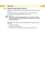
The signal enables the "Cut on demand"
operating mode.
In this case the XSTART signal is checked.
With signal STA disabled the cutter is oper-
ated in the standard mode.
Connect Pin
13 with Pin 12
(GND)
14
RUEL
Reverse line foe all output signals
15
24P
Operating v24 V, 100 mA
CAUTION ! Output !!!
DO NOT connect any external voltage
at Pin 15 !
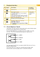
7.3 Circuit Diagram of Inputs
The XSTART and XFEH inputs are optocouplers with a current limiting resistor
of 2.2kΩ giving a voltage of 24V in the input circuit.
For each signal X[IN] there is a separate reverse line X[IN]R via the plug
connector. From that, the following matching pairs of signals result :
Pin 1 - XSTART
Pin 9 - RXSTART
Pin 2 - XFEH
Pin 10 - RXFEH
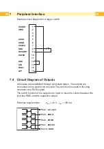
The input signal STA (PIN 13) is connected to GND (PIN 12) for the "Cut on
Demand" operating mode.
For external control of cut mode, the connecting device (trigger switch,
external control) must be equipped with a 15 pin SUB-D connector.

