background image

BOOM


INSTALLATION


Quick


Smart


Mounted


​​

Booms


Only


For


booms


without


Quicksmart™,


bolt


the


boom


to


an


appropriate


surface


using


the


boom


mounting


holes. 

 
With


QSA


Frame; 

Fit


QS


upright


bars


to


centre


frame


of


sprayer


using


M10x30


bolts


and


nuts


supplied.


Fit


with


mounting


lugs


facing 

inwards. 
Fit


sprayer


to


Quicksmart™


frame


and


unfold


arms. 


With


QS


Frame; 

Install


the


Quicksmart™


frame


as


detailed


in


the


mounting


instructions.  

Fit


sprayer


to


Quicksmart™


frame


and


unfold


arms. 

Set


boom


to


required


spraying


height


by


fitting


the


QS


mount


bars


on


the


high


or


low


position,


and/or


adjusting


the 

position


of


the


mount


bars


on


the


centre


frame


of


the


sprayer. 


NOTE


The


QS


upright


bars


can


be


adjusted


in


50mm


increments


on


the


sprayer


centre


frame. 


Boom


Height 

 
Minimum


recommended


boom


height


above


the


​​

target

​​


is


50cm


for


110

0


nozzles


(standard)


and


60cm


for


80

0


nozzles 

(optional). 
Test


the


evenness


of


distribution


by


spraying


an


area


of


dry


concrete


with


clean


water.


​​


The


surface


must


dry


evenly. 

If


the


target


is


above


ground


level,


raise


the


boom


height


accordingly.  


Plumbing


(12V


Pump)


Cut


the


sprayer


output


line


from


the


pump


in


an


easily


accessible


position,


and


install


the


quick


release


valve


with


the 

8.5mm


hose


shank. 

Connect


the


delivery


hose


to


the


boom,


cut


the


hose


to


a


length


so


that


it


can


be


connected


to


the


quick


release


valve 

using


the


10mm


male


hose


shank


connector.   

Connect


the


remainder


of


the


sprayer


output


line


to


the


spray


gun,


to


the


remaining


8.5mm


male


hose


shank 

connector. 


Plumbing


(PTO


or


Engine


Driven


Pump)


Single


Section


Spraying: 

Connect


the


boom


delivery


line


to


a


spare


outlet


port


on


the


sprayer


pressure


regulator,


secure


with


hose


clamps 

provided. 
 
Multi


Section


Spraying: 

Connect


each


spraying


section


boom


delivery


line


to


a


spare


outlet


port


on


the


sprayer


pressure


regulator,


secure


with 

hose


clamps


provided.


Extra


regulator


outlet


ports


are


available


(depending


on


specification). 


THEORY


OF


OPERATION 

 
Spray


fluid


is


placed


in


the


tank


where


it


is


drawn


through


a


suction


filter


and


pumped


to


a


control


valve.


​​


The


excess 

flow


from


the


valve


is


returned


to


the


tank


via


the


bypass


hose.


​​


Fluid


at


a


nominal


pressure


of


1-4


bar


(nominally)


is 

pumped


to


the


spray


tips


via


nozzle


tip


strainers. 

At


the


spray


tip,


fluid


is


atomized


at


the


spraying


pressure


and


the


fluid


is


propelled


toward


the


target


at


the


tip


angle 

(80°


or


110°


nominally). 


Y:\Manuals\Current\90024-3-PNozz.DOC


​​


​​


​​


Содержание Pressure Nozzle Boom Kit

Страница 1: ...OWNER S MANUAL FOR THE PRESSURE NOZZLE BOOM KIT C Dax Systems Ltd P O Box 1010 145 Harts Road Tiritea Palmerston North Ph 64 6 354 6060 Fax 64 6 355 3199 E Mail sales c dax co nz www c dax com...

Страница 2: ...Y Manuals Current 90024 3 PNozz DOC 2...

Страница 3: ...trained in safety This also applies to equipment that is loaned or rented to someone who has not read the owner s manual and is not familiar with the operation of application equipment NEVER EXCEED TH...

Страница 4: ...r a hat long sleeved cotton overalls and boots If you use pesticides regularly it is a good idea to always wear a respirator to avoid cumulative effect Other protection may be required Check the label...

Страница 5: ...nted Booms Only Boom Height Plumbing 12V Pump Plumbing PTO or Engine Driven Theory of Operation 6 Operation Calibrating your Pressure Nozzle Boom 7 Calibration Chart Select Tip Size 8 Spray Tip Select...

Страница 6: ...ced or dismantled by any person other than a service agent or person authorised by C DAX Systems The warranty does not extend to cover consequential damage repair or replacement of parts due to fair w...

Страница 7: ...t line from the pump in an easily accessible position and install the quick release valve with the 8 5mm hose shank Connect the delivery hose to the boom cut the hose to a length so that it can be con...

Страница 8: ...ed you may need to repeat the spraying which will be wasting your money and time Chemicals are expensive Repeat calibration frequently during the seasons to avoid disappointment To calibrate your spra...

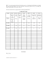
Страница 9: ...g calibration table CALIBRATION CHART NOTES chemical field etc STEP 1 Applicatio n Rate of Chemical litres or kilo per hectare STEP 2 Tank Volume litres STEP 3 Forward Speed KPH STEP 4 Average Nozzle...

Страница 10: ...ax systems endeavours to match the boom output flow to the 12V pump size so there is no need to change the tip size All spray tips supplied by C Dax Systems conform to an international standard for ti...

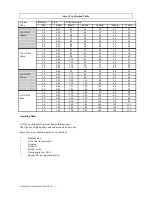
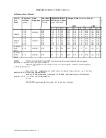
Страница 11: ...0 UF 02 1 5 0 56 112 84 67 56 48 Yellow 2 0 0 65 130 98 78 65 56 2 5 0 73 146 110 88 73 63 3 0 0 80 160 120 96 80 69 3 5 0 86 172 129 103 86 74 4 0 0 92 184 138 110 92 79 1 0 0 69 138 104 83 69 59 110...

Страница 12: ...ly Check the spray tip patterns for wear replace if necessary Calibrate the boom every 100Ha Lubricate any moving boom parts Check spray hoses for kinks or damage replace if necessary Annually Replace...

Страница 13: ...2 0 76 0 71 1 10 1 02 0 95 0 88 1 35 1 25 1 15 1 08 1 1 1 1 V400 4A 8002 pump 4 20 110UF02 0 53 80 64 50 0 62 0 78 1 0 1 0 1 25 1 6 1 V400 4A 8003 pump 4 70 110UF02 0 59 90 71 59 0 55 0 70 0 85 0 88 1...

Страница 14: ...Y Manuals Current 90024 3 PNozz DOC 14...

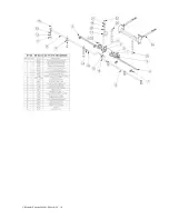
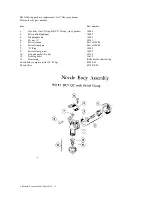
Страница 15: ...and diaphragm 10492 3 Diaphragm only 10493 4 Fly nut 10343 5 Swivel clamp Part of 10480 6 Swivel clamp pin Part of 10480 7 O Ring 10299 9 Swivel clamp screw 10497 10 Cap and gasket No tip 10710 12 Noz...

Страница 16: ...en used successfully in N Z sine 1984 and for over 10 years in the U S A Why C DAXOIL Works C DAXOIL wraps up the chemical in an emulsifiable natural vegetable oil This encapsulation is advantageous t...

Отзывы: