background image

- 6 - 

Install resistors R10 – R13 (1K, brn-blk-red).  These 

limit the current flowing into LEDs D1 – D4. 


Install glass diodes D5 & D6. (1N4148) The black 

stripes should be nearest J1. Bend like resistors. 


Install glass diode D7. (1N4148) The black stripe 

should be nearest LED D1.  Bend like resistors. 


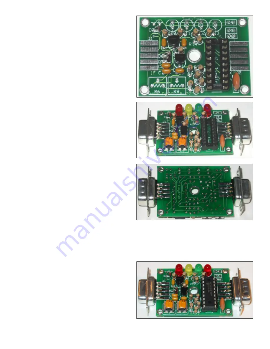
Install potentiometer R6, (10K, 103) which adjusts 

audio output level. 


Install potentiometer R9, (10K, 103) which adjusts 

carrier detect sensitivity. 


Install Power Display LED D1 (red). This LED will 

light when device is powered. Be sure to align the 

flat side of all LEDs with the shape on the silk-

screen, nearest the top edge of the PCB.  


Install Carrier Detect LED D2 (yellow). This LED will 

light constant when audio is detected from the radio 

receiver, and flash during the quiet time before 

transmitting.   


Install GPS State LED D3 (green).  This LED will 

light constant when receiving good (locked) GPS 

data, and flash when receiving bad (unlocked) GPS 

data.  It will be off when no GPS data is received.  


Install PTT LED D4 (red). This LED will light when 

the radio is keyed via PTT.   


Install female DB-9 radio connector J1.  This is the 

connector with the holes.  Wedge the board in 

between the two rows of solder cups, with the 5 

pins aligned with the 5 pads on the PCB. Solder just 

one pin first, and insure the connector is on straight.  

Then solder on both sides of the PCB, all nine cups 

to the pads. 


Install male DB-9 serial connector J2 as you did for J1. This is the connector with the pins.


Assembly Completion 

After all components have been installed, inspect the solder side of the board for poor or cold solder joints.  All pads 

should be shiny and smooth.  Inspect for any undesired solder bridges.  Use an ohmmeter or multimeter to be sure power 

(socket pin 14) and ground (socket pin 5) are not connected.  It would even be a good idea to power the board (see 

below), and c5 volts between socket pins 14 and 5. If the board looks ready, complete the assembly as follows. 


Insert programmed microprocessor U1.  The chip is 

static sensitive, so ground yourself by touching a 

large metal object before touching the chip.  The 

rows of pins may need to be bent slightly.  Be sure 

to align the notch on the chip with the notch on the 

socket, as well as the notch on the silk-screen 

(nearest connector J1).  An improperly inserted chip 

may become permanently damaged. When 

powered, the green and yellow LEDs should flash 3 

times, which means the TinyTrak3 is running. 

Содержание TinyTrak3

Страница 1: ...1 TinyTrak3 Owner s Manual Version 1 0 http www byonics com tinytrak...

Страница 2: ...with altitude speed heading a status message and a timestamp TinyTrak3 can be configured for time slotted reporting or the dynamic reporting rate of SmartBeaconing TinyTrak3 can conserve radio batter...

Страница 3: ...resistor red blk red R4 R10 R11 R12 R13 1K ohm resistor brn blk red R5 220K ohm resistor red red yel R6 R9 10K trimmer potentiometer 103 R7 R14 10K ohm resistor brn blk org R8 2 2K ohm resistor red re...

Страница 4: ...he TinyTrak3Config program Case TinyTrak3 was designed to fit in a Serpac brand C6 plastic case 2 1 4 x 1 5 8 x 3 4 Cases are available from www byonics com but the case must be cut by the owner A nib...

Страница 5: ...t this time Install capacitors C1 C5 0 1uf 104 Direction does not matter If the leads need to be formed to 0 1 inch spacing be careful not to bend too close to the yellow ceramic material Bend the lea...

Страница 6: ...with the holes Wedge the board in between the two rows of solder cups with the 5 pins aligned with the 5 pads on the PCB Solder just one pin first and insure the connector is on straight Then solder...

Страница 7: ...the computer or GPS to the TinyTrak3 J1 pin 5 is serial ground Both a gender changer female to female AND a null modem adapter will be needed to interface the computer to TinyTrak3 A null modem adapt...

Страница 8: ...ch as call signs and transmit rates use the TinyTrak3Config EXE program available from www byonics com First power TinyTrak3 and connect it to a computer serial port Be sure to use a gender changer an...

Страница 9: ...smitter is keyed until the data begins when a transmission is manually triggered via PTT IN It should be set to a value less than the Auto TX Delay when using PTT IN for data burst after voice If PTT...

Страница 10: ...C E format is selected the INVALID flag will be sent in the MIC E data Allow TTL Serial If this option is enabled TinyTrak3 will check the serial input level at power up to determine if it is connecte...

Страница 11: ...seconds TinyTrak3 will synchronize at every 10 minutes If the Auto Transmit rate evenly divides into 60 seconds TinyTrak3 will synchronize at every minute Time slotting and SmartBeaconing are mutuall...

Страница 12: ...is setting selects which communication port the TinyTrak3 is connected to during configuration Currently only the first four serial ports are supported Read Version Button This button will get the cur...

Страница 13: ...justed such that Carrier Detect LED is usually off but turns on when the radio opens squelch Radio receiver volume should be set to maximum and the radio can NOT have a constantly open squelch The las...

Страница 14: ...ak3 in a metal case Try re configuring the settings Sent packets sound distorted on a receiver Be sure the calibration value is around 128 Be sure there is not too much RF energy near the TinyTrak3 Se...

Страница 15: ...Details are at www byonics com Is there a surface mount TinyTrak3 available Not at this time One is currently in the planning stages however Can I replace the ceramic resonator Y1 with a crystal Sure...

Страница 16: ...h no PC connected the GPS serial data will feed into the TinyTrak3 but when the PC is connected the PC will over power the GPS during configuration If you enter a small Transmit Every value you may fi...

Отзывы: