6
Physical Description
EDC-2051 Instruction Manual
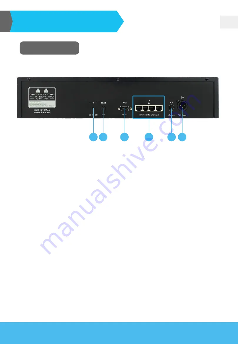
Rear View
1. AUX Output (Unbalance, XLR connector)
Pin 1: Ground
Pin 2: Sound (Aux)
Pin 3: Empty
2. Volume knob for the built-in speaker of the microphone unit
3. LINK 1~4: microphone unit port (RJ45)
4. RS-232 control port (see Appendix for protocol setting):
Pin 2: TXD
Pin 3: RXD
Pin 5: GND
5. DC power supply fuse (DC 250V/8A)
6. Operating voltage DC24V/6A (please use BXB
’s Extension Power Supply-
EA11011M-240
).
Warning: RJ45 microphone unit ports (yellow square part) are not the standard LAN ports.
Please do not plug in other equipment, or the unit would be damaged.
1
2
3
4
5
6


