Page 13 of 38
INSTRUCTION, USE AND
MAINTENANCE MANUAL
GB
2
3
7
4
4
43" 41"
45"
5
1
3
5
3
5
6
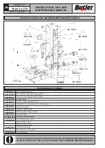
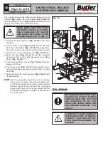
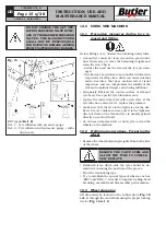
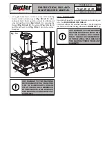
The column is moved by unloosing the fixing screws of
the base (
Fig. 12 ref. A
) to the column (
Fig. 12 ref. B
)
and by sliding the base (
Fig. 12 ref. A
) itself into the
proper slots until the required measure.
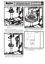
MAKE SURE THAT THE TYRE-
CHANGER COLUMN IS STABLE:
USE A CABLE HELD BY A HOIST
AND HOOK THE CABLE TO THE
COLUMN ITSELF
(
FIG. 13 REF. 7
)
.
1. Remove the lateral guard (
Fig. 13 ref. 1-2
) of the
machine.
2. Unscrew the screws (
Fig. 13 ref. 3
) and the nuts
near the central slots (
Fig. 13 ref. 4
) paying atten-
tion not to remove the nuts from the proper screws.
3. Remove the six remaining screws (
Fig. 13 ref. 5
).
4. Move the base (
Fig. 13 ref. 6
) into the required
position (to 43” or 45”) and if necessary, use a lifting
device (
Fig. 13 ref. 7
).
5. Lock the base three screws (
Fig. 13 ref. 3
) with a
couple of 80 Nm.
6. Place six screws (
Fig. 13 ref. 5
) previously remo-
ved and lock them on the bases side with a couple
of 80 Nm.
7. Assemble again the lateral guards (
Fig. 13 ref. 1-2
)
of the machine.
NOTE:
after the assembly, check the correct position
of the tools. Lock the rim on the mandrel cen-
tre. With the bead breaker arm, check that the
distance between the roll and the rim edges
(upper and lower) is the same. Repeat all the
procedures starting from point 1 if the distance
is not the same.
Fig. 13
10.5 Controls
BEFORE STARTING UP THE TYRE-
CHANGER, BE SURE TO BECOME
FAMILIAR WITH THE LOCATION
AND OPERATION OF ALL CON-
TROLS AND CHECK THEIR PRO-
PER OPERATION (SEE PAR. “CON-
TROLS”).
CARRY OUT A DAILY CHECK OF
MAINTAINED-TYPE CONTROLS
CORRECT FUNCTIONING, BE-
FORE STARTING MACHINE OP-
ERATION.
SEIDO.30 - SEIDO.30FI
7105-M005-10_B


