INSTRUCTION, USE AND
MAINTENANCE MANUAL
GB
Page 29 of 68
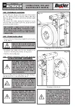
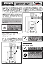
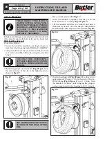
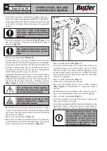
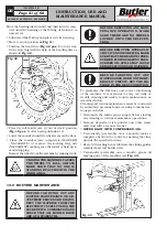
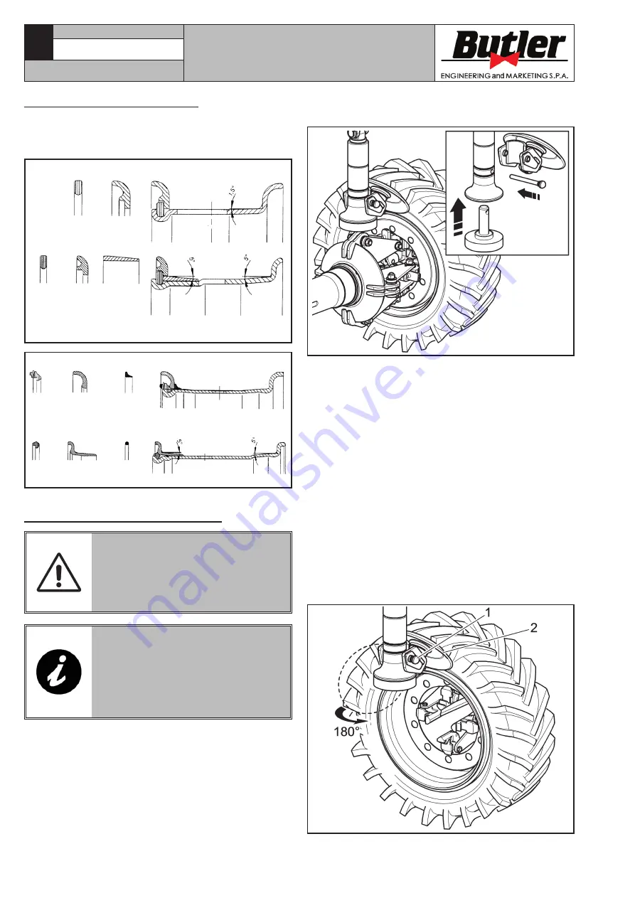
• Mount the accessory (as shown in
Fig. 39
) and posi-
tion the beading disc on rim edge (see
Fig. 39
).
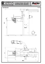
Fig. 39
• Turn the mandrel and smear the entire bead seat
of the rim with lubricant. While doing this, jerk the
beading disc forward until the first bead is removed
(as these wheels feature inner tubes, carry out the
operation carefully, paying special attention to when
the bead dislodges, trying to stop disc advancement
immediately to avoid compromising the integrity of
the inner tube and valve).
• Bring the roll holder arm in “out of work” position
(
Fig. 18 pos. 1
); by operating on the handle control
position the roll holder arm on the external side of
the wheel then bring it back into “working” position
(
Fig. 17 pos. 1
) and lock it with the special safety pin.
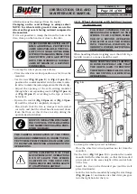
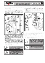
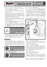
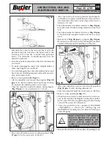
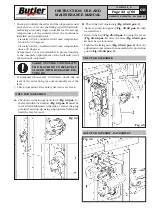
• Remove the pin (
Fig. 40 pos. 1
), turn the beading
disc (
Fig. 40 pos. 2
) with 180° rotation and lock it
again with the pin (
Fig. 40 pos. 1
) in order to be
able to bring the beading disc itself in contact with
the external side of the tyre (see
Fig. 40
).
Fig. 40
7503-M002-6_B
NAV26HW - NAV26HW.S - NAV26HW.ST
12.9 Wheels with bead wire
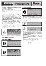
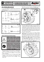
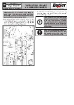
As an example
Fig. 37
and
38
illustrate sections and
compositions of types of wheels with bead wire cur-
rently being sold.
Fig. 37
Lock
ring
Lock
ring
Non split
side ring
Non split
side ring
Tapered
bead seat
ring
Three-piece flat base rim and pertinent rings for
tubed tyres and SOLID tyres
Four-piece 5” tapered bead seat rim and perti-
nent rings for tubed and SOLID tyres
Fig. 38
Lock
ring
Lock
ring
Non split
ring
Non split
ring
Rubber seal-
ing ring
O-sealing
ring
12.9.1 Beading and demounting
NEVER STAND IN FRONT OF THE
WHEEL WHILE THE INFLATION
RING IS BEING EXTRACTED FROM
THE BEAD WIRE, SINCE IT MAY BE
EJECTED VIOLENTLY, CAUSING
SERIOUS INJURIES OR WOUNDS.
THROUGHOUT TYRE MOUNT-
ING/DEMOUNTING OPERATIONS,
CHECK THAT THE SELF-CENTRING
MANDREL CLAMPING PRESSURE
IS CLOSE TO THE MAXIMUM
OPERATING VALUE (130 BAR)
(NAV26HW - NAV26HW.S).
• Mount the wheel on the mandrel as described in
“WHEEL CLAMPING” and make sure it is deflated.
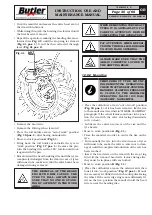
• Move to work position
C
(
Fig. 11
) with G108A22
fixture (optional).
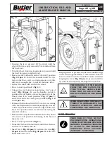
• Place the roll holder arm in “working position” (
Fig.
17 pos. 1
) in the tyre inner side, and make sure it
is locked by the provided safety stop (
Fig. 1, 2
and
3 pos. 12
).

