INSTRUCTION, USE AND
MAINTENANCE MANUAL
GB
Page 14 of 68
10.0 WORKING ENVIRONMENT CONDI-
TIONS
The machine must be operated under proper condi-
tions as follows:
• temperature: 0° + 55° C
• relative humidity 30 - 95% (dew-free)
atmospheric pressure: 860 - 1060 hPa (mbar).
The use of the machine in ambient conditions other
than those specified above is only allowed after prior
agreement with and approval of the manufacturer.
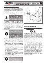
10.1 Working position
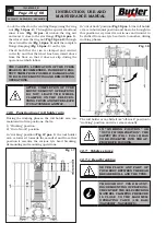
In
Fig. 11
it's possible to define working positions
A,
B, C
which will be referred to in the description of
machine operative phases.
Positions
A
and
B
must be considered as main posi-
tions for tyre mounting and demounting and for wheel
clamping on the mandrel, while positions
A
and
C
are
the best positions to follow tyre bead breaking and
demounting operations.
Working in these positions allows better precision and
speed during operating phases as well as greater safety
for the operator.
10.2 Working area
Fig. 11
INSTALL THE MACHINE INDOORS OR IN A
ROOFED AREA. PLACE OF INSTALLATION
MUST BE DRY, ADEQUATELY LIT AND IN
COMPLIANCE WITH APPLICABLE SAFETY
REGULATIONS.
7503-M002-6_B
NAV26HW - NAV26HW.S - NAV26HW.ST
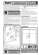
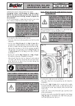
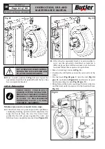
Then horizontally or vertically move the lever (
Fig. 13
pos. E
): the red LED (
Fig. 13 pos. B
) will flash.
Wait a few seconds for the green LED to turn on (
Fig.
13 pos. A
) and then release the lever (
Fig. 13 pos. H
).
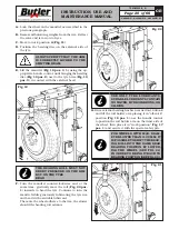
In the end, the green LED (
Fig. 13 pos. A
) flashes to
indicate that the machine is ready for operation.
WHEN A CONTROL IS OPERATED,
THE GREEN LED (FIG. 13 POS.
A) LIGHT IS FIXED: IT FLASHES
AGAIN WHEN IT IS RELEASED.
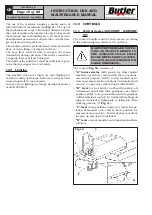
If during the operations the red LED (
Fig. 13 pos. B
)
and the green LED (
Fig. 13 pos. A
) turn on at the same
time, charge the control batteries with the provided
socket for battery charger, located on the control side
(
Fig. 13 pos. G
).
The machine is equipped with a device for the interrup-
tion of the communication between the control and the
electrical panel, when more than 6 hours have passed
after the last executed control. In this case, just repeat
the turning on operations described in the “Electrical
checks” chapter.
NAV26HW - NAV26HW.ST
KEY
A - Main switch
B - Direction rotation of oil-pressure power unit
motor
C - Selector 1-0-2 self-centring chuck speed con-
trol (only for VARGNAV26HWD - version with
inverter)
Fig. 10
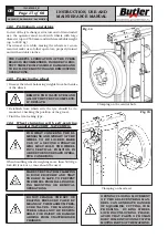
ONCE THE ASSEMBLY OPERA-
TIONS HAVE BEEN ENDED, CHECK
ALL MACHINE FUNCTIONS.


