
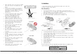
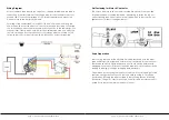
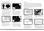
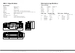


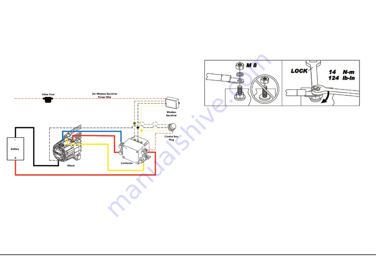
Wiring Diagram
Attach the black lead firmly to the negative (–) battery terminal and red lead to
the positive (+) battery terminal. The voltage drop for the winch motor must not
exceed 10% of the nominal voltage of 12V. For best performance, mount the
winch as close to the battery as possible.
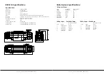
For wiring of the wireless receiver on REVO 10S and 12S models, a 2m long red
power wire with inline fuse exits out of the control box and should be connected
to a switched power source. We recommend connection to the vehicles ignition
or accessories circuits, which will allow for the wireless to be used only when the
vehicle is turned on. Another option is to run it through a dash mounted on/off
switch so that the user can turn the wireless function on and off as required.
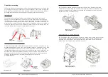
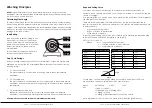
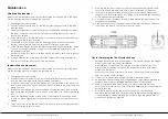
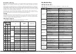
The nuts on the motor and contactor should be fastened to the s pecified
torqueas outlined in the diagram below. Attempting to fasten the top nut
without locking the bottom nut could result in damage to the studs. Do not
tighten top nut without locking bottom nut.
Nut Fastening for Motor & Contactor
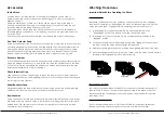
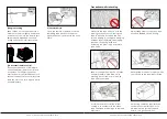
Rope Preparation
Prior to using the rope for the first time, it must be tensioned onto the drum
under load to ensure a tight and uniform wrap is achieved. A rope that is not
tensioned and wound tightly and evenly prior to use can be permanently
damaged since the outer layers of rope can draw down into the inner layers
leading to binding, pinching or wedging between layers.
One method for tensioning the rope onto the drum is to use the weight of the
vehicle on a slight incline to pull on the rope while spooling in. This can be
achieved by following the steps outlined in the following section “Winching
Procedures” (Page 14). Prior to spooling in under this load, ensure the rope is
pulled out to leave the minimum amount of wraps
| REVO VEHICLE RECOVERY WINCH
|REVO VEHICLE RECOVERY WINCH
Page 9
Page 10
Содержание REVO 10
Страница 1: ...REVO 10S REVO 10W REVO 12S REVO 12W ...
Страница 24: ......


