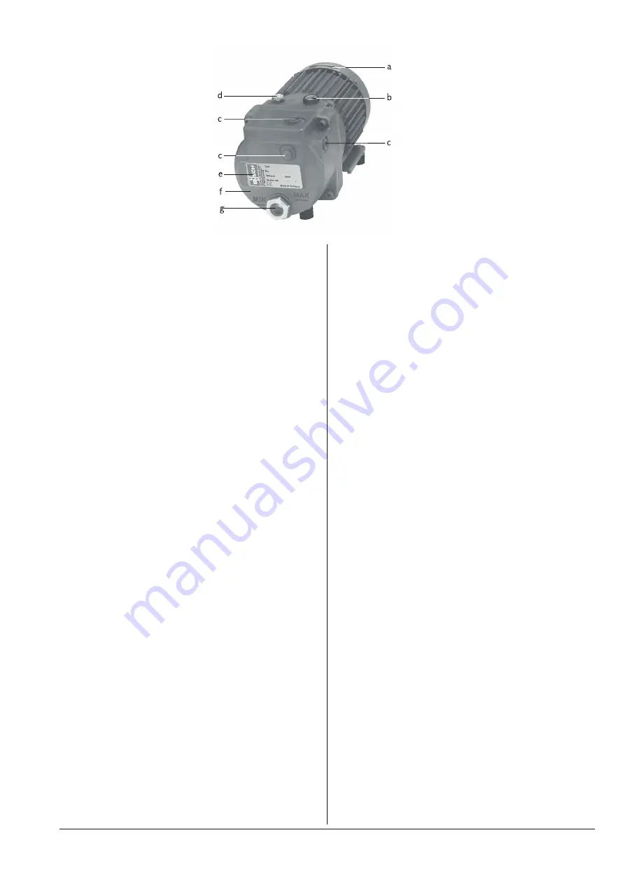
Product Description
Use
The vacuum pump is intended for
–
the suction
of
–
air and other dry, non-aggressive, non-toxic and non-explosive
gases
Conveying media with a lower or higher density than air leads to an in-
creased thermal and/or mechanical load on the vacuum pump and is
permissible only after prior consultation with Busch.
In case the vacuum pump is equipped with a gas ballast (optional) wa-
ter vapour within the gas flow can be tolerated within certain limits
(
page 8: Conveying Condensable Vapours). The conveyance of
other vapours shall be agreed upon with Busch.
The vacuum pump is intended for the placement in a non-potentially
explosive environment.
Version with oil return line to the suction connection (RC 0006 C/E):
The vacuum pump is thermally suitable for continuous operation
(100 percent duty).
Version with oil return valve (RB 0006 C/E):
The vacuum pump is thermally suitable for continuous operation (ob-
serve the notes with regard to the oil recirculation:
page 3: Oil Cir-
culation;
page 8: Oil Return).
The vacuum pump is ultimate pressure proof.
Principle of Operation
The vacuum pump works on the rotating vane principle.
A circular rotor is positioned centrically on the shaft of the vacuum
pump (i.e. drive motor shaft).
The rotor rotates in an also circular, fixed cylinder, the centreline of
which is offset from the centreline of the rotor such that the rotor and
the inner wall of the cylinder almost touch along a line. Vanes, sliding
in slots in the rotor, separate the space between the rotor and the cyl-
inder into chambers. At any time gas is sucked in and at almost any
time ejected. Therefore the vacuum pump works almost pulsation free.
In order to avoid the suction of solids, the vacuum pump is equipped
with a screen in the suction connection.
In order to avoid reverse rotation after switching off, the vacuum
pump is equipped with a non-return valve.
Note
: This valve shall not be used as a non-return valve or shut-off
valve to the vacuum system and is no reliable means to prevent suction
of oil into the vacuum system while the vacuum pump is shut down.
In case the vacuum pump is equipped with a gas ballast (optional):
Through the gas ballast a small amount of ambient air is sucked into
the pump chamber and compressed together with the process gas. This
counteracts the accumulation of condensates from the process gas in-
side the vacuum pump (
page 8: Conveying Condensable Vapours).
The gas ballast line is equipped with a paper filter.
Oil Circulation
The vacuum pump requires oil to seal the gaps, to lubricate the vanes
and to carry away compression heat.
The oil reservoir is located on the pressure side of the vacuum pump
(i.e. high pressure) at the bottom of the bottom chamber of the oil
separator (f).
The feed openings are located on the suction side of the vacuum pump
(i.e. low pressure).
Forced by the pressure difference between pressure side and suction
side oil is being drawn from the oil separator (f) through the oil supply
lines and injected on the suction side.
Together with the sucked gas the injected oil gets conveyed through
the vacuum pump and ejected into the oil separator (f) as oil mist. Oil
that separates before the exhaust filter accumulates at the bottom of
the bottom chamber of the oil separator (f).
Oil that is separated by the exhaust filter accumulates at the bottom of
the upper chamber of the oil separator (f).
The flow resistance of the exhaust filters causes the inside of the ex-
haust filters (which is connected to the bottom chamber of the oil sep-
arator) to be on a higher pressure level than the outside of the exhaust
filters (i.e. the upper chamber of the oil separator). Because of the
higher pressure in the bottom chamber it is not possible to let oil that
drips off the exhaust filters simply flow down to the bottom chamber.
Version with oil return line to the suction connection (RC 0006 C/E):
Therefore the oil that accumulates in the upper chamber is sucked
through the oil return line right to the suction connection.
Version with oil return valve (RB 0006 C/E):
At continuous operation this would cause the entire supply of oil to ac-
cumulate at the bottom of the upper chamber, expel oil droplets
through the gas discharge/pressure connection and let the vacuum
pump run dry. Therefore the vacuum pump must be shut down at the
latest after 0.5 hours of continuous operation, depending on the oper-
ating conditions even after a shorter period, for at least approx. 5 min-
utes (
page 7: Operation Notes). After turning off the vacuum pump
the pressure difference between the inside and the outside of the ex-
haust filter(s) collapses, hence the two chambers of the oil separator
assume an equal pressure level, the oil return valve between the two
chambers opens and the accumulated oil in the upper chamber can run
down to the bottom chamber.
Cooling
The vacuum pump is cooled by
–
radiation of heat from the surface of the vacuum pump incl. oil
separator (f)
RB/RC 0006 C/E
Product Description
0870152229
page 3
a
Directional arrow
b
Oil fill plug
c
Suction connections
d
Gas discharge
e
Nameplate
f
Oil separator
g
Oil sight glass
Содержание R5 RB 0006 C
Страница 20: ......


