(the standard non-return valve that is installed inside the suction con-
nection is not meant to be used for this purpose!)
If the vacuum pump is planned to be used for the suction of gas that
contains limited quantities of condensable vapour:
Provide a shut-off valve, a drip-leg and a drain cock in the suc-
tion line, so that condensates can be drained from the suction
line
Make sure that the suction line does not contain foreign objects,
e.g. welding scales
Gas Discharge
The discharged gas must flow without obstruction. It is not permitted
to shut off or throttle the discharge line or to use it as a pressurised
air source.
The following guidelines for the discharge line do not apply, if the aspi-
rated air is discharged to the environment right at the vacuum pump.
CAUTION
_a
The discharged gas contains small quantities of vacuum oil.
Staying in vacuum oil contaminated air bears a risk of damage to
health.
If air is discharged into rooms where persons stay, sufficient ventila-
tion must be provided for.
Make sure that the discharge line fits to the gas discharge (d) of
the vacuum pump
In case of using a pipe:
Make sure that the pipe will cause no stress on the vacuum
pump’s connection, if necessary use an expansion joint
Make sure that the line size of the discharge line over the entire
length is at least as large as the gas discharge (d) of the vacuum
pump
In case the length of the discharge line exceeds 1 m it is prudent to use
larger line sizes in order to avoid a loss of efficiency and an overload of
the vacuum pump. Seek advice from your Busch representative!
Make sure that the discharge line either slopes away from the
vacuum pump or provide a liquid separator or a drip leg with a
drain cock, so that no liquids can back up into the vacuum pump
WARNING
_ad
Discharge lines made from non-conductive material can build up
static charge.
Static discharge can cause explosion of potentially existing oil
mist.
The discharge line must be made of conductive material or provi-
sions must be made against static discharge.
Electrical Connection / Controls
Make sure that the stipulations acc. to the EMC-Directive
2004/108/EC and Low-Voltage-Directive 2006/95/EC as well as
the EN-standards, electrical and occupational safety directives and
the local or national regulations, respectively, are complied with
(this is the responsibility of the designer of the machinery into
which the vacuum pump is to be incorporated;
page 18: note in
the EC-Declaration of Conformity).
Make sure that the power supply for the drive motor is compatible
with the data on the nameplate of the drive motor
Make sure that an overload protection according to EN 60204-1 is
provided for the drive motor
Make sure that the drive of the vacuum pump will not be affected
by electric or electromagnetic disturbance from the mains; if neces-
sary seek advice from the Busch service
In case of mobile installation:
Provide the electrical connection with grommets that serve as
strain-relief
Installation
Mounting
Make sure that the installation prerequisites (
page 5) are com-
plied with
Set down or mount the vacuum pump at its location
Connecting Electrically
WARNING
_ab
Risk of electrical shock, risk of damage to equipment.
Electrical installation work must only be executed by qualified per-
sonnel that knows and observes the following regulations:
- IEC 364 or CENELEC HD 384 or DIN VDE 0100, respectively,
- IEC-Report 664 or DIN VDE 0110,
- BGV A2 (VBG 4) or corresponding national accident prevention
regulation.
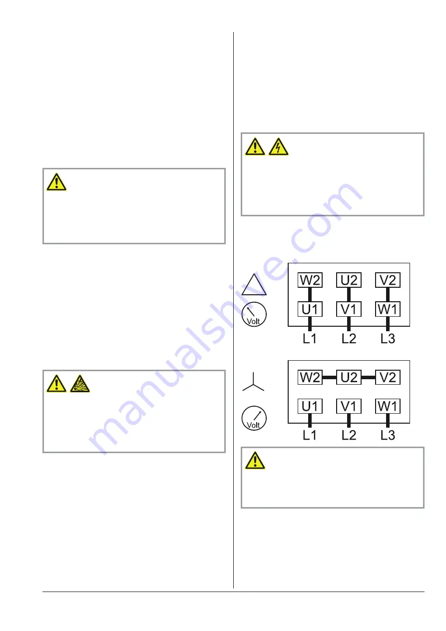
Electrically connect the drive motor
Connect the protective earth conductor
Connection Scheme Three-Phase Motor
Delta connection (low voltage):
Star connection (high voltage):
CAUTION
_a
Operation in the wrong direction of rotation can destroy the
vacuum pump in short time.
Prior to starting-up it must be made sure that the vacuum pump is
operated in the proper direction.
Version with three-phase motor:
Determine the intended direction of rotation with the arrow
(stuck on or cast)
“Bump” the drive motor
Watch the fan wheel of the drive motor and determine the di-
rection of rotation just before the fan wheel stops
If the rotation must be changed:
Switch any two of the drive motor wires (three-phase motor)
Installation and Commissioning
page
6
RB/RC 0006 C/E
0870152229
Содержание R5 RB 0006 C
Страница 20: ......


