5
9.11.6
Displaying the lowest and highest values measured ................................................................50
9.11.7
Setting the display contrast and brightness ...............................................................................50
9.11.8
Choosing the output wiring mode .................................................................................................51
9.11.9
Setting the parameters of the current outputs ...........................................................................51
9.11.10 Setting the parameters of the transistor outputs .......................................................................53
9.11.11 Setting the sensor parameters .......................................................................................................54
9.12
Knowing the calibration menu ...................................................................................................................................55
9.12.1
Activating/deactivating the Hold function ....................................................................................55
9.12.2
Modifying the Calibration menu access code ............................................................................56
9.12.3
Adjusting the current outputs .........................................................................................................56
9.12.4
Calibrating the pH sensor ...............................................................................................................57
9.12.5
Calibrating the Redox- ("ORP"-) sensor ......................................................................................61
9.12.6
Entering an offset for the temperature measurement ...............................................................64
9.13
Knowing the Diagnostic menu ...................................................................................................................................64
9.13.1
Modifying the Diagnostic menu access code ............................................................................64
9.13.2
Monitoring the condition of the probe ..........................................................................................64
9.13.3
Monitoring the fluid temperature ....................................................................................................66
9.14
Knowing the test menu .................................................................................................................................................67
9.14.1
Modifying the Test menu access code .........................................................................................67
9.14.2
Checking the outputs functions .....................................................................................................67
9.14.3
Checking the outputs behaviour .....................................................................................................67
9.15
Knowing the information menu .................................................................................................................................68
9.15.1
Reading the cause of events linked to icons ..............................................................................68
9.15.2
Reading the software versions ........................................................................................................68
9.15.3
Reading some identification informations of the device ............................................................68
10
mAintenAnce AnD troubleshooting .....................................................................................................................69
10.1
safety instructions ............................................................................................................................................................69
10.2
cleaning the device ..........................................................................................................................................................69
10.2.1
Cleaning the pH/Redox ("ORP") probe .......................................................................................70
10.3
replacing the probe .........................................................................................................................................................70
10.4
replacing the seal of the sensor holder ...............................................................................................................72
10.5
solving a problem .............................................................................................................................................................73
English
Type 8202 ELEMENT
Страница 1: ...Operating Instructions Bedienungsanleitung Manuel d utilisation Type 8202 ELEMENT pH or redox meter pH oder Redox Messger t pH ou redox m tre...
Страница 2: ...ve the right to make technical changes without notice Technische nderungen vorbehalten Sous r serve de modifications techniques B rkert SAS 2008 2021 Operating Instructions 2106 06_EU ML 00560329 Orig...
Страница 3: ...on 11 5 2 Construction of the 8202 11 5 3 pH or Redox ORP probe 11 5 4 Type label 12 6 Technical data 13 6 1 Conditions of use 13 6 2 Conformity to standards and directives 13 6 2 1 Conformity to the...
Страница 4: ...35 9 1 Safety instructions 35 9 2 Knowing the operating levels 35 9 3 Using the navigation button 36 9 4 Using the dynamic functions 38 9 5 Entering a numerical value example 38 9 6 Browsing in a men...
Страница 5: ...ture measurement 64 9 13 Knowing the Diagnostic menu 64 9 13 1 Modifying the Diagnostic menu access code 64 9 13 2 Monitoring the condition of the probe 64 9 13 3 Monitoring the fluid temperature 66 9...
Страница 6: ...6 11 Spare parts and accessories 78 12 Packaging Transport 79 13 Storage 79 14 Disposal of the 79 English Type 8202 ELEMENT...
Страница 7: ...Instructions refers to the Type 8202 ELEMENT pH meter and redox meter 1 2 Validity of the Operating Instructions The Operating Instructions are valid for the Type 8202 ELEMENT pH meter and redox meter...
Страница 8: ...as intended 3 Basic safety information This safety information does not take into account any contingencies or occurrences that may arise during instal lation use and maintenance of the device The op...
Страница 9: ...not subject the device to mechanical stress Do not make any modifications to the device Prevent any unintentional power supply switch on Only qualified and skilled staff may carry out the installatio...
Страница 10: ...sales offices are available on the internet at country burkert com 4 2 Warranty conditions The condition governing the legal warranty is the conforming use of the device in observance of the operatin...
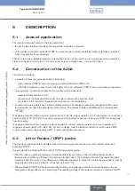
Страница 11: ...The display module is available as an accessory see chpt 11 One device variant with two transistor outputs and a 4 20 mA output operates on a 2 wire system and requires a power supply of 14 36 V DC F...
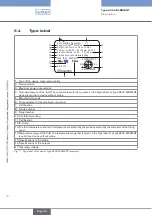
Страница 12: ...he Type label of a Type 8202 ELEMENT device is valid for a device without probe 5 Manufacturing code 6 Pin assignment of the electrical connection 7 Certification 8 Article number 9 Serial number 10 C...
Страница 13: ...plied standards which verify conformity with the EU directives can be found on the EU type examination certificate and or the EU declaration of conformity if applicable 6 2 1 Conformity to the Pressur...
Страница 14: ...e 4 Paragraph 1 a ii PS 1000 bar 6 2 2 UL certification The devices with variable key PU01 or PU02 are UL certified devices and comply also with the following standards UL 61010 1 CAN CSA C22 2 n 6101...
Страница 15: ...Display module PC PBT M12 male connector M12 female connector nickel plated brass stainless steel on request Support plate of the M12 male connector or M12 female connector PPS CF30 Screws stainless...
Страница 16: ...he related Operating Instructions pH measurement Measurement range 2 16 pH or 580 580 mV Resolution 0 001 pH or 0 1 mV Measurement deviation 0 02 pH or 0 5 mV Recommended min divergence of the pH rang...
Страница 17: ...3 12 11 10 9 8 7 6 5 4 3 2 1 0 0 20 40 60 T C P bar PVC PP 20 232 217 6 203 188 6 174 159 6 145 130 6 116 101 6 87 72 5 58 43 5 29 14 0 P psi Metal P Fluid pressure T Fluid temperature Fig 4 Dependenc...
Страница 18: ...ith loads on the transistors 1 A max Power consumption 40 W max Protection against polarity reversal yes Protection against voltage spikes yes Transistor output polarized type NPN or PNP Through wirin...
Страница 19: ...xed connector 5 pin female M12 connector not supplied and 5 pin male M12 connector not supplied For the M12 connector with article number 917116 use a shielded cable diameter 3 6 5 mm wire cross secti...
Страница 20: ...the installation Guarantee a set or controlled restarting of the process after any intervention on the device 7 2 Removing the housing lid Notice The tightness of the device is not guaranteed when th...
Страница 21: ...unting the display module Notice The tightness of the device is not guaranteed when the housing lid is removed Prevent the projection of liquid inside the housing The device may be damaged if a metal...
Страница 22: ...sher seal Following instructions are valid for a B rkert probe If you use a probe from another supplier respect the related instructions Remove the protective plugs Check that dimension H on the probe...
Страница 23: ...with alcohol to avoid measurement errors Insert the electronic module into the holder making sure the polarising slots are correctly positioned Apply slight vertical pressure to engage the seal Fasten...
Страница 24: ...erve the dependency between the fluid temperature and the fluid pressure Risk of burns due to high fluid temperatures Use safety gloves to handle the device Before opening the pipe stop the circulatio...
Страница 25: ...d without temperature probe from a supplier other than B rkert is used follow the relevant instructions on installation in the pipe Direction of the fluid Choose an appropriate position in the pipe to...
Страница 26: ...l Fig 14 Removing the electronic module from the sensor holder Install the holder with its probe on the fitting as shown in Fig 15 B Check the presence and the condition of seal B on the fitting Repla...
Страница 27: ...efer to chpt 11 and chpt 10 4 Insert the electronic module into the holder making sure the polarising slots are correctly positioned Apply slight vertical pressure to engage the seal Fasten the electr...
Страница 28: ...s wired set the HWMode parameter depending on the wiring carried out sink NPN or source PNP Refer to chpt 9 11 8 8 3 1 Assembling the male or female connector accessories 4 3 2 1 Unscrew the nut 1 on...
Страница 29: ...r valves that is as close as possible to the device Refer to Fig 19 Power supply 12 36 V DC Metal pipe Fig 18 Equipotentiality skeleton diagram with pipes in metal Power supply 12 36 V DC Equipment su...
Страница 30: ...ow or grey 14 36 V DC 1 2 3 4 Load 1 solenoid valve for instance Load 2 solenoid valve for instance Power supply white blue black brown green yellow or grey Fig 21 NPN wiring of both transistor output...
Страница 31: ...Load 1 4 20 mA input at external device brown green yellow or grey blue white black Power supply Fig 24 NPN wiring of both transistor outputs and wiring the current output in sinking mode software set...
Страница 32: ...order to ease wiring of the load to the female fixed connector Pin of the M12 female cable available as an accessory article number 438680 Colour of the wire 1 brown 2 white 3 blue 4 black 5 green ye...
Страница 33: ...at external device brown blue green yellow or grey 2nd 4 20 mA input at external device black brown black Fig 29 Wiring of both current outputs in sinking mode on a device variant with 2 fixed connect...
Страница 34: ...sinking mode on a device variant with 2 fixed connectors software setting NPN sink see chpt 9 11 8 12 36 V DC 1 2 3 4 3 2 1 4 Load 1 1st 4 20 mA input at external device brown green yellow or grey bl...
Страница 35: ...e pH Redox ORP sensor Refer to chpt 9 12 4 Before start up make sure that the staff in charge have read and fully understood the contents of the Operat ing Instructions In particular observe the safet...
Страница 36: ...Diagnostic see chpt 9 13 Test see chpt 9 14 Info see chpt 9 15 9 3 Using the navigation button Symbolised by in these Operat ing Instructions Symbolised by in these Operating Instructions Symbolised...
Страница 37: ...t the highlighted function browse in the dynamic functions bar MEAS BACK ABORT OK YES NO next function previous function confirm the highlighted dynamic function modify a numerical value increment the...
Страница 38: ...BORT answer the question asked dynamic function YES or NO 9 5 Entering a numerical value example 0 000 C Select the digit at the extreme left of the numerical value with then allocate the or sign to t...
Страница 39: ...ow indicates that some more functions are available which can be displayed by using Title of the current menu sub menu or function Highlighted function The icon identifies the current menu This is whe...
Страница 40: ...oard that is located under the display module these LEDs can only be seen if the device has no dispaly module Icon Possible cause and alternatives Probe in good condition and fluid temperature within...
Страница 41: ...V_pH 1423 mV TempC 55 C mV_pH 1423mV 18 3 mA AC1 7 5 mA AC2 A 1 1 1 First view of the Process level Zoom on the value in the first line Zoom on the value in the second line AC1 18 3 mA AC2 7 5 mA A Di...
Страница 42: ...his is when the device is be ing parame tered Param 2s Calib This is when the device is be ing parame tered Info This is when the device is be ing parame tered Diagnostic Test Any display of the Proce...
Страница 43: ...tered This is when the device is be ing parame tered Factory reset pH TempC Line1 Line2 Filter None Fast Slow Enabled Line1 Line2 PVar Reset Yes No Disabled Downl Yes No Upload Yes No Contrast xx Bac...
Страница 44: ...y open Normal closed INPUT Low INPUT High INPUT pH TempC mV_pH mV_ORP TempF Outputs HWMode sink NPN source PNP PVar pH TempC mV_pH mV_ORP TempF Mode Hysteresis Window Sensor Type pH ORP This is when t...
Страница 45: ...Offset INPUT INPUT Span If pH probe Calib Temp Auto Constant Diagnostic System Code 0 Confirm code 0 Glass electrode Sensor Impedance Activate Yes No READ Warn high INPUT Warn low INPUT Err high INPUT...
Страница 46: ...de 0 Test Value Sensor INPUT Outputs AC2 AC1 INPUT INPUT TR1 OFF ON TR2 OFF ON Info Error MESSAGE MESSAGE Warning MESSAGE Maintenance MESSAGE Smiley Main Sensor READ READ PVar pH TempC mV_pH mV_ORP Te...
Страница 47: ...another device of the same type user set data of the PARAM menu except the date the time the contrast and brightness levels for the display user set data of the DIAGNOSTIC menu the TDS factor set in...
Страница 48: ...Process level and the outputs See chpt 9 9 to access the Parameters menu The following data can be restored to their default values user set data of the PARAM menu except the date the time the contras...
Страница 49: ...when the device is be ing parame tered pH TempC Line1 Line2 Filter None Fast Slow Enabled Line1 Line2 PVar Disabled mV_pH mV_ORP TempF pH C Unit mV F If PVar TempC If PVar TempF If PVar mV_pH or mV_OR...
Страница 50: ...t or the power up of the device PVAR choose the measurable variable which highest and lowest measured values are displayed in the Process level UNIT choose the preferred unit in which the lowest and h...
Страница 51: ...8 3 Wiring 9 11 9 Setting the parameters of the current outputs See chpt 9 9 to access the Parameters menu Warning Risk of injury due to wrong adjustment Before setting the parameters for the display...
Страница 52: ...A for each current output FILTER choose the level of damping for the fluctuations of the current value for each current output Three damping levels are proposed slow fast or none The damping for the c...
Страница 53: ...sistor output 2 respectively If the selected transistor output is linked to the warning event the transistor switches as soon as such an event is generated by the device See also chpt 10 5 Solving a...
Страница 54: ...ected NO Normally open NC Normally closed ON OFF contact Low High process value ON OFF contact Low High process value Fig 39 Window operating 9 11 11 Setting the sensor parameters The monitoring see c...
Страница 55: ...2 Fig 41 Schematic diagram of asymmetrical measurement MAINS FCY choose the frequency of your mains electricity 50 or 60 Hz This frequency is filtered by the device to ensure stable measurements 9 12...
Страница 56: ...requested to access the menu 9 12 3 Adjusting the current outputs See chpt 9 9 to access the Calibration menu On a device variant with a single M12 fixed connector and if the power supply is lower tha...
Страница 57: ...alue select constant then enter reference temperature Calibrate the sensor using one of the following methods CALIBRATION calibrate the pH sensor in 1 or 2 points see details hereafter A calibration p...
Страница 58: ...see above each time a calibration is due the device generates a maintenance event and a warning event 1 point calibration The 1 point calibration procedure is used for quick calibration by adjusting t...
Страница 59: ...H 7 000 pH Cal Result Offset 10 70 mV Span 0 0mV pH The device displays the calibration result OK Cal Result Save Yes No Error Span offset out of range Probe Warning Span offset out of range See Tab 1...
Страница 60: ...an offset out of range 50 mV pH span 53 mV pH or 63 mV pH span 65 mV pH 60 mV Offset 35 mV or 35 mV Offset 60 mV Error in the buffer solution Use the correct buffer solution The probe has reached half...
Страница 61: ...nt then enter reference temperature Calibrate the sensor using one of the following methods CALIBRATION calibrate the Redox ORP sensor in 1 point see page 63 A calibration process updates the last cal...
Страница 62: ...the electrode with a suitable product Set the periodicity of calibrations in the Interval function in the sub menu CALIB INTERVAL see heretofore each time a calibration is due the device generates a...
Страница 63: ...OK Cal Result Save Yes No Error Span offset out of range Probe Warning Span offset out of range see Tab 2 for the possible cause of the warning message OK OK At the end of calibration of the oxidatio...
Страница 64: ...sted to access the menu 9 13 2 Monitoring the condition of the probe See chpt 9 9 to access the Diagnostic menu Diagnostic Glass electrode Sensor Impedance Activate Yes No READ Warn lo INPUT Err hi IN...
Страница 65: ...ce values for each electrode in order to identify the cause of an out of range impedance if necessary clean then recalibrate the measurement probe or replace it The warning event may also be associate...
Страница 66: ...the cause of the event generation and or go into the Sensor function of the Diagnostic menu to read the measured temperature value then check whether the built in Pt1000 is working correctly by measu...
Страница 67: ...that current output 2 is working correctly by entering a current value and then selecting OK TR1 check that transistor output 1 is working correctly by selecting the status of the transistor ON or OFF...
Страница 68: ...or See also chpt 10 5 Solving a problem 9 15 2 Reading the software versions See chpt 9 9 to access the Info menu Info Main Sensor READ READ Software The function allows for reading the software vers...
Страница 69: ...of burns due to high fluid temperatures Use safety gloves to handle the device Before opening the pipe stop the circulation of fluid and drain the pipe Before opening the pipe make sure the pipe is c...
Страница 70: ...n and safety regulations for electrical equipment Risk of injury due to pressure in the installation Before any intervention in the installation stop the circulation of fluid cut off the pressure and...
Страница 71: ...ght resistance due to the seal Unscrew the probe using a suitable wrench Remove it carefully from the holder Clean any fluid projections on the electrical contacts on the holder Fig 42 Removing the pr...
Страница 72: ...o the standard UL EN 61010 1 Observe all applicable accident protection and safety regulations for electrical equipment The seal can be replaced without dismounting the holder from the pipe Refer to F...
Страница 73: ...to B rkert ON 22 mA depending on thresholds ERR S EE User Read User data for the sensor is lost eg type of sensor Switch the power supply off then on again Check the sensor param eters in all the Sens...
Страница 74: ...e error persists set the device back to the default settings chpt 9 11 4 If the error persists return the device to B rkert OFF 4 20 mA depending on thresholds S Diff pH ORP S Buff Diff pH S Buff Diff...
Страница 75: ...d depending on the set thresholds ERR LO and ERR HI see chpt 9 13 2 Go into the Sensor function of the Diag nostic menu to read the impedance value of the pH electrode chpt 9 13 2 If necessary clean t...
Страница 76: ...g on the set thresholds WARN LO and WARN HI see chpt 9 13 3 Go into the Sensor function of the Diag nostic menu to read the impedance value of the pH electrode chpt 9 13 3 If necessary clean then reca...
Страница 77: ...lib Date A calibration is due The periodicity of the cal ibrations is set within the INTERVAL function of the CALIB INTERVAL menu see chpt 9 12 4 Calibrate the sensor chpt 9 12 4 2 If the PVAR functio...
Страница 78: ...pH probe 0 14 pH 10 60 C 0 6 bar LOGOTRODE pH 120 mm 427114 pH probe 0 14 pH 0 130 C 0 6 bar UNITRODE PLUS pH 120 mm 560376 pH probe 0 14 pH 0 130 C 0 16 bar CERATRODE pH 120 mm 418319 pH probe 0 14 p...
Страница 79: ...e plugs 13 Storage Notice Poor storage can damage the device Store the device in a dry place away from dust Storage temperature of the device without probe 10 60 C Storage temperature of the device wi...
Страница 80: ...80 English Type 8202 ELEMENT...
Страница 81: ......
Страница 82: ...www burkert com...