background image

GAS 222.20

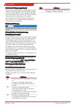
4.5.2 Connecting the calibrating gas line (optional)

Connecting the calibrating gas line requires a Ø6 mm or Ø1/4”
pipe fitting.

If the calibrating gas connection was ordered with check
valve, a Ø6 mm or Ø1/4” pipe can be connected directly to the
check valve.

4.6 Electrical connections

WARNING

Hazardous electrical voltage

The device must be installed by trained staff only.

CAUTION

Wrong mains voltage

Wrong mains voltage may damage the device.

Regard the correct mains voltage as given on the type plate.

Electric strength test

The necessary tests of all assemblies required to be tested
were carried out at the factory (test voltage 1 kV or 1.5 kV de-
pending on component).

To check the electric strength again yourself, only do so on the
respective individual components.

• Now perform the electric strength test against earth.

4.6.1 Connection via Terminal Strip

The probe has regulated, adjustable heating. The supply
voltage is 115 V AC, 50/60Hz or 230 V AC, 50/60 Hz (see type
plate).

The device is already wired to the controller.

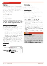
Inside the controller housing is a terminal block for connect-
ing the mains supply and the alarm output. The connection to
the included terminal blocks is shown in the attached connec-
tion diagram. For this purpose the plugs can be removed from
their sockets and reinserted once wired. The pin assignment is
also printed onto the board.

If the heat dissipation is very high near the probe due to the
application, the customer must install a shield to protect the
probe and regulator.

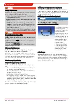
4.6.2 Heated Extension (Optional)

The unit can optionally be ordered with heated extension.
Heated via regulated heating tape with Pt100, preventing fall-
ing below the sample gas dew point at the sample point. The
unit cannot be retrofit with a heated extension.

The connection cable for the heated extension (mains connec-
tion 115 or 230 V AC) must be connected per the enclosed con-
nection diagram.

5 Operation and Control

NOTICE

The device must not be operated beyond its specifications.

5.1 Basic function of the probe controller

5.1.1 Regulator Functions

After switching on the combination the probe is heated up.
The display with the current temperature will light up on the
controller. As long as the set operating range is has not yet
been reached, the display will flash and the status contact is
in Alarm position. Once the working range has been reached,
the status contact switches and the display is steady.

The target temperature, the working range of the probe and
the temperature unit (°C/°F) are set using the three control
buttons on the controller. This is described in chapter “Opera-
tion and use”.

The factory settings are: Unit: °C; target temperature: 180 °C;
working range: ±10 °C

5.1.2 Advanced Functions with Built-In Regulator for
Heated Extension (Optional)

The display will alternating between "Prob"– adapter temper-
ature – "AdOn"– extension temperature.

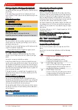
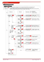
5.2 Use of menu functions

Overview of the operational principal:

Use this short description if you have experience with the
device.

Operation is carried out by only the keys with the following
functions:

Key

Function

• Switch from measurement display to main

menu

• Selection of the display menu item
• Accepting the changed value or selection

• Switch to the upper menu item
• Increase of the value of switching the selection
• Temporary display of the alternative measure-

ment display (if option is installed)

• Switch to lower menu item
• Decrease of the value of switching the selection
• Temporary display of the alternative measure-

ment display (if option is installed)

10

Bühler Technologies GmbH

BX460040 ◦ 10/2019

Содержание GAS 222.20

Страница 1: ...040 Version 10 2019 Ref 998BX460040 Analysentechnik Kurzanleitung Sonden deutsch 2 Brief Instructions Probes english 8 Notice de montage Sondes fran ais 13 Gu a r pida Sondas espa ol 19 chinese simpli...

Страница 2: ...n Sie beim Anschluss die Kennwerte des Ger tes und bei Ersatzteilbestellungen die richtigen Ausf hrungen 1 2 Typenschild Beispiel GAS 222 20 100107323 462220009902000112213 001 230V 50 60Hz 440W mater...

Страница 3: ...Voraussetzungen bestimmt Falls m glich sollte der Einbaustutzen eine leichte Nei gung zur Kanalmitte haben Der Einbauort sollte wettergesch tzt sein Ebenfalls muss auf ausreichenden und sicheren Zuga...

Страница 4: ...n gesundheitssch dlich sein Pr fen Sie die Leitungen auf Dichtheit 4 5 2 Anschluss der Kalibriergasanschlussleitung optional Zum Anschluss der Kalibriergasleitung wird eine Rohrver schraubung 6 mm bzw...

Страница 5: ...bereich der Sonde und die Temperatureinheit C F werden mittels der drei Bedientas ten der Steuerung eingestellt Dies ist im Kapitel Betrieb und Bedienung beschrieben Die Werkseinstellungen sind Einhei...

Страница 6: ...ahlweise Celsius oder Fahrenheit Anzeige Temperatur Wahlmen Wahlmen Exit Wahlmen Exit Anzeige Top Settings R cksp lintervall Alarm Wahlmen Sondentemperatur R cksp lzeit ____ Einstellbereich Setzen der...

Страница 7: ...der Ori ginalbetriebsanleitung auf der beigef gten CD oder im Inter net unter www buehler technologies com 7 Service und Reparatur Eine ausf hrliche Beschreibung des Ger tes mit Hinweisen zur Fehlers...

Страница 8: ...1 x Sample gas probe 1 x Flange gasket and screws Product documentation Connection and mounting accessories only optional 2 Safety instructions The equipment must be installed by a professional famil...

Страница 9: ...ectly When seated correctly it locks onto the filter housing 4 4 Insulation On heated probes completely insulate any exposed flange areas and if applicable the connection piece to absolutely prevent t...

Страница 10: ...ple gas dew point at the sample point The unit cannot be retrofit with a heated extension The connection cable for the heated extension mains connec tion 115 or 230 V AC must be connected per the encl...

Страница 11: ...rature Selection menu Selection menu Exit Selection menu Exit Display Top Settings Blowback interval Alarm Selection menu Probe temperature Blowback time ____ Setting range Setting the alarm hysteresi...

Страница 12: ...r s manual on the included CD or online at www buehler technologies com for maintenance informa tion 7 Service and Repair Please refer to the original operator s manual on the included CD or online at...

Страница 13: ...a d signation de type Veuillez respecter les valeurs caract ristiques de l appareil lors du branchement et veillez commander les bonnes pi ces de rechange 1 2 Plaque signal tique Exemple Fabricant ave...

Страница 14: ...e montage sont d termin s en fonc tion des conditions d application pertinentes Le support de montage doit avoir si possible une l g re inclinaison vers le milieu du conduit Le lieu d installation doi...

Страница 15: ...yst me d analyse Apr s avoir branch toutes les conduites et contr l l tanch it l isolation doit tre remise en place et fix e avec pr cautions AVERTISSEMENT Fuite de gaz Le gaz de mesure peut tre dange...

Страница 16: ...affichage est permanent La temp rature de consigne la zone de travail de la sonde et l unit de temp rature C F sont r gl es au moyen de trois touches de maniement de la commande Ceci est d crit au cha...

Страница 17: ...Temp rature Menu de s lection Menu de s lection Exit Menu de s lection Exit Affichage Top Settings Intervalle de r trolavage Alarme Menu de s lection Temp rature de sonde Dur e de r trolavage ____ Pla...

Страница 18: ...ns le mode d emploi original pr sent sur le CD fourni ou sur Internet en allant sur www buehler technolo gies com 7 Service et r paration Vous trouverez une description d taill e de l appareil ainsi q...

Страница 19: ...lo Tenga en cuenta los valores caracter sticos del aparato para la conexi n y los modelos correctos para encargar repuestos 1 2 Placa de caracter sticas Ejemplo Fabricante y direcci n Denominaci n N d...

Страница 20: ...plicaci n Si es posible el tubo de montaje debe presentar una lige ra inclinaci n hacia la mitad del conducto El lugar de instalaci n no debe quedar a la intemperie Adem s debe asegurarse de que el ac...

Страница 21: ...colocar y a fijar el aislante con gran cuidado ADVERTENCIA Salida de gas El gas de medici n puede resultar nocivo para la salud Compruebe que los conductos no presenten fugas 4 5 2 Conexi n del conduc...

Страница 22: ...peratura de ajuste la zona de trabajo de la sonda y la unidad de temperatura C F se establecen mediante los tres botones del sistema de control Esto aparece detallado en el cap tulo Uso y funcionamien...

Страница 23: ...ra Men de selecci n Men de selecci n Salir Men de selecci n Salir del submen Pantalla Top settings Intervalo de retrolavado Alarma Men de selecci n Temperatura de sondas Tiempo de retrolavado ____ Opc...

Страница 24: ...se pueden encontrar en el CD que se incluye y en Internet www buehler technologies com 7 Servicio y reparaci n Para obtener una descripci n m s detallada del dispositivo y recomendaciones recomendaci...

Страница 25: ...gen Deutschland 49 0 2102 4989 0 49 0 21 02 49 89 20 1 1 ID 1 2 GAS 222 20 100107323 462220009902000112213 001 230V 50 60Hz 440W material 1 4571 1 4408 PTFE Read manual 1 3 1 x 2 a b c d a b c 3 20 C...

Страница 26: ...8 1 6 mm 1 4 2 NPT 1 4 G1 2 NPT 1 4 G1 8 G1 4 NPT 1 4 1 1 2 GAS 222 xx ANSI GAS 222 xx AMEX 4 5 1 NPT 1 4 4 5 2 6 mm 1 4 6mm 1 4 4 6 1 kV 1 5 kV 4 6 1 115 V AC 50 60Hz 230 V AC 50 60 Hz 4 6 2 Pt100 1...

Страница 27: ...GAS 222 20 5 1 2 Prob AdOn 5 2 3 27 B hler Technologies GmbH BX460040 10 2019...

Страница 28: ...ALAr E ___ C F C 5s 50 C 200 C 122 F 392 F ____ 5 C 30 C 50 C 200 C 122 F 392 F 5 C 30 C 5s 99s Blow back controller AdOn bbc tEMP ALAr E E ____ ___ __ __ __ 0 5 min 99h59min 5 59 s ctrl tInt t_bb 28...

Страница 29: ...GAS 222 20 6 CD www buehler technologies com 7 CD www buehler technologies com 29 B hler Technologies GmbH BX460040 10 2019...

Страница 30: ...H Harkortstra e 29 40880 Ratingen Deutschland 49 0 21 02 49 89 0 49 0 21 02 49 89 20 1 1 o 1 2 GAS 222 20 100107323 462220009902000112213 001 230V 50 60Hz 440W material 1 4571 1 4408 PTFE Read manual...

Страница 31: ...GAS 222 20 a b c d 3 20 C 50 C 4 F 122 F 4 4 1 4 2 4 3 90 4 4 31 B hler Technologies GmbH BX460040 10 2019...

Страница 32: ...PN6 DN3 150 2 G3 4 NPT 1 4 G3 8 1 6 1 4 2 NPT 1 4 G1 2 NPT 1 4 G1 8 G1 4 NPT 1 4 1 1 2 GAS 222 xx ANSI GAS 222 xx AMEX 4 5 1 NPT 1 4 4 5 2 6 1 4 6 1 4 4 6 1 1 5 4 6 1 115 AC 50 60 230 AC 50 60 32 B h...

Страница 33: ...GAS 222 20 4 6 2 Pt100 115 230 AC 5 5 1 5 1 1 C F C 180 C 10 C 5 1 2 Prob AdOn 5 2 3 33 B hler Technologies GmbH BX460040 10 2019...

Страница 34: ...F 392 F Exit Exit Top Settings ____ 5 C 30 C 50 C 200 C 122 F 392 F 5 C 30 C 5 99 Add on Blow back controller AdOn bbc tEMP ALAr Exit E Exit E ____ ___ __ __ __ 0 5 99 59 5 59 ctrl tInt t_bb Control m...

Страница 35: ...GAS 222 20 6 www buehler technologies com 7 www buehler technologies com 35 B hler Technologies GmbH BX460040 10 2019...

Страница 36: ...ed extension Pt100 heated extension Pt100 probe Power supply extension heated extension Power supply extension Blowback status Blowback solenoid valve Status Automatic Manual Sample gas solenoid valve...

Отзывы: