INSTALLATION INSTRUCTIONS & PARTS FOR THE MOREFLEX COUPLING
ALIGNMENT OF TURBINE SHAFT WITH SHAFT OF ENGINE IS CRITICAL
1.
Install keys in both shafts.
2.
Slide coupling flanges on both shafts (engine and turbine shafts)
3.
Place Morflex coupling CENTER SECTION between coupling flanges and secure with 4 bolts and
TOPLOC nuts. The bolt heads are positioned against the coupling in alternating directions. Tighten all
4 bolts. DO NOT TIGHTEN SET SCREWS AT THIS TIME.
4.
Check key for proper position under the set screw hole on both shafts.
5.
Place several drops of Loctite 271 into these two holes only. Set screws and tapped screw holes must
be free of dirt and oil for Loctite to work properly.
6.
Install the set screws over the keys and tighten firmly.
7.
Using a drill point, dimple each shaft through the other 2 set screw holes. Clean drill chips, oil and dirt
before applying Loctite.
8.
Place several drops of Loctite 271 in these 2 holes.
9.
Install and tighten set screws in these 2 holes.
10.
Check and retighten the 4 bolts that hold the coupling center section in place.
11.
Visually inspect the unit and replace the guard. DO NOT OPERATE WITHOUT THE GUARDS IN
PLACE.
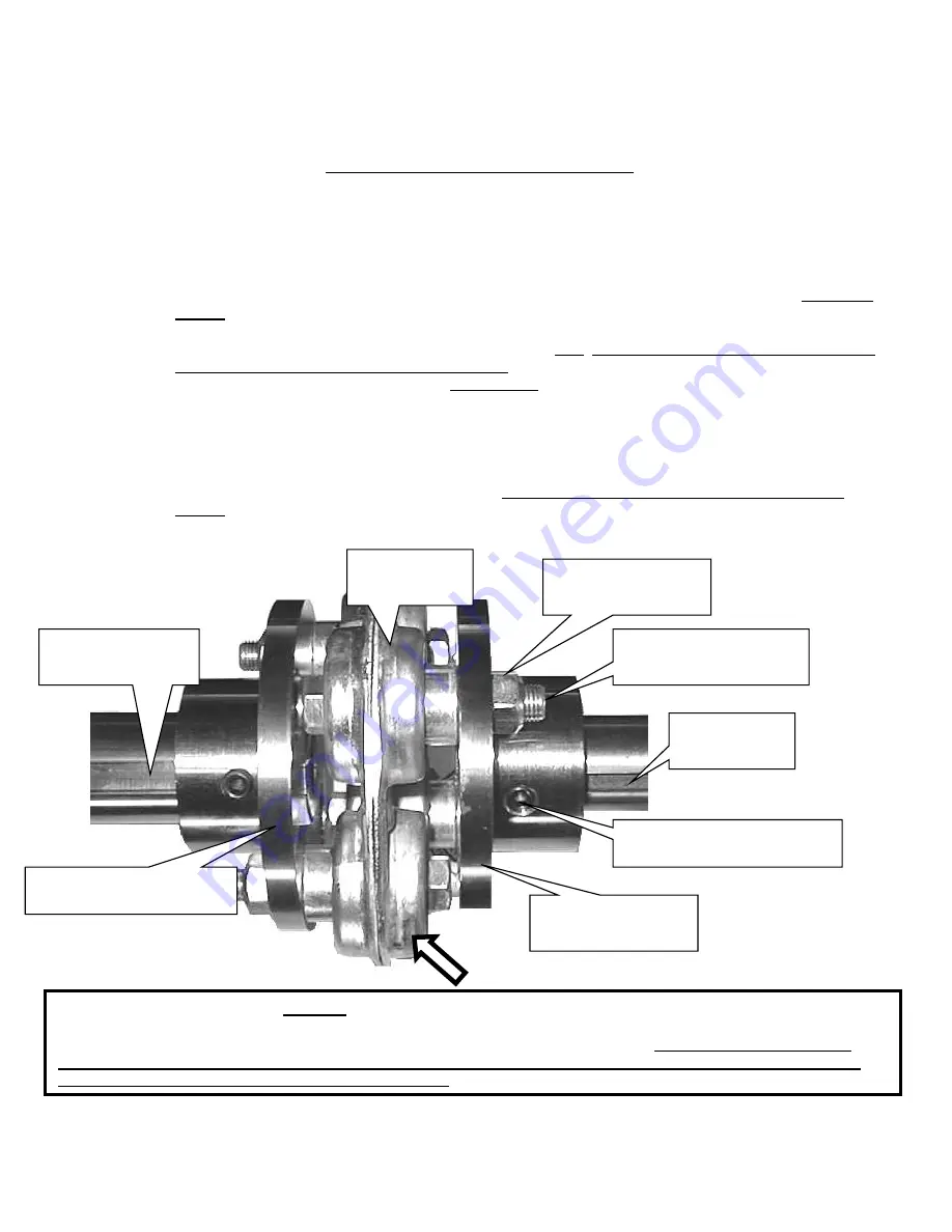
COUPLING COMPLETE, KOHLER ENGINE
PN 1110(1pc), 3805 (1pc), 1112(4pc), 1113(4pc), 1114(1pc), 1115(1pc), 1256(1pc), 2869(4pc)
Coupling flange, 1 7/16” bore
Engine - #1115
Coupling flange, 1 ¼
Turbine - # 1114
7/16 –20 TopLoc Nut
(4) required - #1112
7/16-20 x 2 ½ HHCS
Zinc – (4) required - #1113
Center Section
#1256
Key – Engine
3/8 - #3805
Key – Turbine
¼ x 1 ¾ - #1110
7/16-20 x 3/8" Socket Set Screw
# 2869
Part # 1256 (center section) is a
“WEAR”
item that should be visually checked each time the engine oil is changed. This
coupling is equipped with special lock nuts. Occasionally check that all 4 nuts are securely fastened. LOOK FOR
CRACKS IN THE RUBBER COMPOSITION THAT SURROUNDS THE 4 BUSHINGS.
Replace the center section
when the rubber composition begins to show ANY signs of cracking OR an increase in vibration OR unusual
sounds. When in doubt, call our Service Department.
Содержание BT-CS4
Страница 11: ...11 4 4 MODEL BT CS4 Assembly Instructions ...
Страница 12: ...12 ...
Страница 21: ...21 ...
Страница 22: ...22 ...
Страница 23: ...23 ...
Страница 24: ...24 ...
Страница 25: ...25 ...
Страница 26: ...26 ...
Страница 27: ...27 ...
Страница 28: ...28 ...
Страница 29: ...29 ...
Страница 30: ...30 ...
Страница 31: ...31 ...
Страница 32: ...32 ...
Страница 33: ...33 ...
Страница 34: ...34 ...


