background image

Position setting 


SMART MATRIX MTC 

2 - 37


Position setting 


This function allows you to set: 

1. 

LDRUM

: the drum length (development), i.e. the length of yarn that will be wound on the bobbin during 

every stroke. The value may range between 1 mm and 5000 mm and it may be associated to all the 
installed sensors, or you may want to assign different values to specific sensor ranges. Depending on 
the set value, the system will automatically calculate the number of strokes needed to obtain the Target, 
according to the following formula: 


Number of strokes


= Target x 1000 

 LDRUM 

2. 

KANTIP

the correction factor in the yarn length calculation if a constant error due to a bobbin slippage 

or to a different drum size is detected (KANTIP = Anti-pattern factor). To the measured value, it will be 
possible to either add or subtract a percentage value ranging between –25.0% and +25.0%. In this case 
the number of strokes needed to obtain the Target will be calculated according to the following formula

 Number of strokes


= Target x 1000   +/- KANTIP. 

 LDRUM 


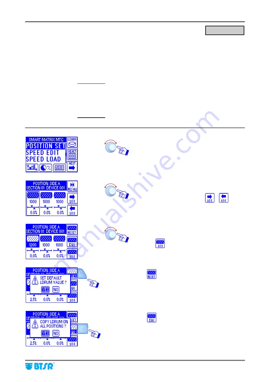
Select the 

POSITION SET 

menu item

.


Select the first device and press one time to set the 

LDRUM 

value. Press again to set the 

KANTIP 

value. 

If there are many sensors, use the 

 e 

 keys to 

move forward and backward 10 sensors a time.  


Set the development value of cylinder (

e.g. 

LDRUM

=1200 mm

)  

Press the 

 key to increase the value 10 mm a 

time. 


Press 


to set the 

LDRUM

 default value and 

confirm with 

YES


Press 

 to copy the set 

LDRUM

 value to all the 

other sensors and confirm with 

YES


POSITION SET 

Содержание SMART MATRIX MTC

Страница 1: ...SMART MATRIX MTC Operating Manual ENGLISH Rev 1 0 September 2010 ...

Страница 2: ...any time the contents of this Manual without notice For any technical or commercial problem please contact your local BTSR dealer or call directly BTSR customer service center We will be glad to meet your needs Thank you for your trust and good job The product described herein is compliant with the requirements of EMC 2004 108 CE and Low Voltage Directive 2006 95 CE All BTSR products are covered b...

Страница 3: ...Introduction i ...

Страница 4: ......

Страница 5: ...l S p A to make easier and optimize The sensor programming The system configuration The production monitoring The availability of a User Friendly graphic interface allows you to quickly and intuitively program all the operating parameters of IS3W MTC sensors in addition it provides a real time monitoring of sensors behavior and production efficiency Manual Objectives This manual has been written t...

Страница 6: ...es the main characteristics and performances of the various system components IS3W MTC sensors SM DIN MTC boards DAC devices Furthermore it provides some details to better understand the operating principles upon which the SMART MATRIX MTC system is based Symbols Used This symbol is used to point out notes warnings and other important information MTC Within this manual the IS3W MTC sensors used fo...

Страница 7: ...RT MATRIX MTC Menu Structure 2 8 Sensor Configuration and Numbering 2 9 DACS devices Configuration and Numbering option 2 12 Smart Matrix Code 2 13 Input Output Configuration on SM DIN Smart Matrix 2 14 Speed Setting option 2 16 Keycode Setting 2 17 Communication Test 2 19 Sensor Test 2 20 DAC devices test option 2 21 Sensor Firmware Upgrade 2 22 DAC Firmware Upgrade option 2 23 SM DIN MTC Board F...

Страница 8: ...in RS485 devices technical characteristics option 3 1 SMART MATRIX SMDIN MTC Board technical characteristics 3 2 ID and Transmission Speed Configuration on Each SM DIN Board P01 P02 Parameters 3 3 IS3W MTC Sensor Features 3 4 Function of the IS3W MTC Sensors 3 4 Interface Specifications 3 5 ...

Страница 9: ...Connections and Electrical Interface 1 ...

Страница 10: ......

Страница 11: ...graphs SMART MATRIX SM DIN IS3W MTC Connection and Sensor Interface Prior to operate the SMART MATRIX terminal make sure you have programmed the communication speed on all the SM DIN MTC Boards as well as on CV232 485 9 module For more details please refer to paragraph SMART MATRIX SM DIN PC Interface on Section 1 and to paragraph ID and Transmission Speed Configuration on Each SM DIN Board on Sec...

Страница 12: ...IX SM DIN IS3W MTC Connection The following diagram shows the connection of IS3W MTC Sensors to SM DIN Boards as well as the connection between SM DIN Boards and SMART MATRIX MAX 100 SENSORS MAX 100 SENSORS FLAT CABLE CONNECTION EXAMPLE MA2 FE FORK CABLE CONNECTION EXAMPLE ...

Страница 13: ...DIN Machine Interface The following diagram shows the electrical interface pin assignment of SM DIN Board The sensor interface is shown on the following page Recommended power supply 24 Vdc Machine Interface INPUT Machine Interface OUTPUT Power Supply ...

Страница 14: ...tion As you may note 4 identical connectors are available allowing you to connect up to 4 IS3W MTC The number of IS3W sensors actually connectable to the Board depends on the capacity of power supply system used Sensors Sensors Sensors Sensors Max 100 IS3W MTC sensors SM DIN nn Module Identified by means of Edt function directly on the SM DIN module ...

Страница 15: ... press the small P button SMART MATRIX Terminal Technical Characteristics Power supply voltage 24 VDC 10 Current absorption 100 mA Max Protection fuse SMART MATRIX 1 5 A Protection fuse Sensor power supply 1 5 A 0 24 VDC VIL Max 1 2 VDC Inputs VIH Min 5 VDC Operating temperature range 10 60 C Storage temperature 25 85 C Overall dimensions 140x80x31 mm 1 As STOP output it is advisable to use the Re...

Страница 16: ...ATRIX QUILT Generic Application Diagram SMART MATRIX MTC 1 6 SMART MATRIX MTC Generic Application Diagram The MACHINE STOP signal can be obtained either from the SM DIN Boards or from the SMART MATRIX terminal ...

Страница 17: ...Operating Instructions 2 ...

Страница 18: ......

Страница 19: ...s etc graphic information sensors map etc B 6 buttons for immediate activation of particular functions increment decrement speed up shortcuts C Multi function Rotary Selector How to Use the Rotary Selector The selector provides both pointing and data entry functions Turn the selector to select a menu item function parameter within the configuration screens etc Rapid click to confirm the selection ...

Страница 20: ...nal can be carried out using exclusively the multi function Rotary Selector through a navigation technique based upon Pointing Selecting and Value Setting actions The following example explains this navigation technique The example refers to the Modify function on STYLE EDIT menu which makes use of 2 windows STD and ADV 1 Name label of currently selected window foreground 2 Name label of non selec...

Страница 21: ...lick to Select the pointed item The field name will be shown in reverse and the symbols appear to the right of the field value Example TARGET field selected reverse Turn the selector either to Clockwise or to Counter clockwise direction to select the desired option in this case the numerical value chosen Example New value of TARGET 1200 Once you have set the desired value e g 1200 click to confirm...

Страница 22: ...indow STD and click to select it Esempio Î Label STD highlighted Turn the selector to Point the ADV window ATD ADV Î Label OUT highlighted Click to select the ADV window and enable the access to its parameters Select the desired parameter as explained on previous paragraph 1 Navigation inside the Selected Window STD ...

Страница 23: ...o choose the first letter of the name Click to confirm Turn the selector to choose the second letter of the name Click to confirm The sequence of characters shown turning the selector is the following A B C X Y Z 0 1 2 9 space A B C etc 4 Parameters Saving Once you have setup all the desired parameters within a determined function press and hold down 3 seconds the rotary selector SAVE to save the ...

Страница 24: ...he various function will be provided on next paragraphs The following examples are only provided to summarize the Button Function association Within some configuration parameter setting functions the B1 B6 buttons may also perform a shortcut function which will be explained each time Immediate function activation buttons B1 Sensors Histogram B2 Efficiency Data B3 Alarms Counters B4 LEARN Activatio...

Страница 25: ...cted Broken yarn failure BROKE detected by sensor No 04 DEV 04 mounted on section No 1 SECT 01 machine side No 1 SIDE A Î Press to scroll the list of sensors in alarm Target detected on sensor No 04 DEV 04 mounted on section No 1 SECT 01 machine side No 1 SIDE A Î Press to scroll the list of sensors in alarm Alternating Alternating ...

Страница 26: ... be used Turn the selector to point the desired option Select the desired option and click to confirm Press and hold down the button 3 sec to return to previous menu and or to activate the data saving function Error Alternating Error details Main Menu Style Database management Style Loading System Configuration Position set Speed Database management Speed Loading ...

Страница 27: ...number of SM DIN MTC Boards used 1 10 3 in this example Point the symbol of 1st Board Select the field indicating the number of sensors connected to Board 1 default 100 Set the number of sensors actually connected to Board 1 e g 6 and confirm Point the symbol of 2nd Board and so on for all the Boards used Once you have configured all the Boards For instance let suppose now to configure an applicat...

Страница 28: ...e green led will flash on all sensors Shim the touch light of the sensor corresponding to SIDE A SECT 01 DEVICE 01 The sensor s led changes from flashing green to red On SMART MATRIX display the DEVICE SECTION and SIDE fields will automatically increase to select one by one the sensors to be numbered Shim the touch light of the relevant sensor and continue with the numbering of all sensors At the ...

Страница 29: ...ll the operations described for sensor configuration and numbering until the start numbering screen appears Select the position of sensor to be re numbered SIDE XX SECT NN DEVICE NN Shim the touch light of the relevant sensor the sensor s led changes from flashing green to red To quit the identification procedure after the sensor re numbering EXIT to return to configuration menu ...

Страница 30: ...OFF if no DAC is connected SAVE to save the settings and startup the numbering procedure The example shown indicates that the numbering identification procedure of the 5 DACs is going to begin The green led will flash on all DACs Shim the touch light of the DAC corresponding to CURRENT 001 The sensor s led changes from flashing green to red On SMART MATRIX display the CURRENT field will automatica...

Страница 31: ...nals The identification code is required for Upgrade operations Enter the SETUP menu Select MATRIX CODE Choose the SMART MATRIX identification code and activate the save function SAVE to save the choice BACK to return to the previous screen without saving EXIT to return to menu Since the SMART MATRIX MTC application uses only one terminal always set 1 as identification code SETUP MATRIX CODE ...

Страница 32: ... It also allows you to configure the output relay MATRIX option of SMART MATRIX terminal as normally open NO or normally closed NC contact Enter the SETUP menu Select I O CONFIG Select BOARDS Configure the input signals IN 1 IN 2 IN 3 IN 4 within the IN window and the output signals STOP1 STOP2 within the OUT window as NO or NC To activate the save function SAVE to save the choice BACK to return t...

Страница 33: ...art Matrix SMART MATRIX MTC 2 15 Select MATRIX Configure the output relay of SMART MATRIX terminal as NO or NC To activate the save function SAVE to save the choice BACK to return to the previous screen without saving EXIT to return to menu ...

Страница 34: ... square wave forms supplied by DAC devices Enter the SETUP menu Select SPEED SETUP In the CHANNEL 1 window set the maximum speed of channel 1 range 1 to 2500 m min default 500 m min Select the CHANNEL 2 window and repeat the previous instructions E g 800 m min To activate the save function SAVE to save the choice BACK to return to the previous screen without saving EXIT to return to menu SETUP SPE...

Страница 35: ...menus and options it also allows you to remove clear users and to change the list of accessible menus and options You cannot set two users with the same name or with the same password Enter the SETUP menu Select KEY CODE Add New User Press the indicated button to add a new user Set the new user name e g USER 1 and password e g PASS 1 in the ACCOUNT windows Select the menus and options available to...

Страница 36: ...e access rights of selected user Change the configuration of menus and options available to the selected user SETUP MENU STYLE LOAD STYLE EDIT DAC STYLE LOAD DAC STYLE EDIT POSITION SET METER READ COUNTERS READ EFFICIENCY When you try to access a password protected function the following prompt will appear Choose the user name and set the password to access the selected function When the password ...

Страница 37: ...T COM Select COMM EFF to check the efficiency level of communications Select GLOBAL global efficiency or SINGLE communication efficiency with each sensor Number of sensors on which communication errors occurred DEV IN ERROR and total number of transmission repeated as result of detected errors TOTAL RETRY A maximum of 5 transmission are repeated for each sensor Global efficiency index Like for GLO...

Страница 38: ... to previous menu EXIT TEST MODE will appear for a few seconds If the GLOBAL Test shows an error e g 001 005 which means that one sensor does not correctly communicate with the system then operate as follows 1 Run the SINGLE Test to locate the Board which the defective sensor is connected to 2 Select the Sensor Test and confirm the correct red Led blinking the sensor which does not show the red le...

Страница 39: ...the SETUP menu Select TEST COM Select DAC TEST ENTER TEST MODE will appear for a few seconds Select the DAC device you want to test the selected DAC shall have the led blinking To return to previous menu EXIT TEST MODE will appear for a few seconds SETUP TEST COM DAC TEST ...

Страница 40: ...e the firmware of IS3W sensors Enter the SETUP menu Select SERVICE Select MTC UPG Select the range of sensors on which you want to upgrade the FIRMWARE default All To continue UPGRADE to start the upgrading Automatic scanning of sensors to be upgraded Automatic upgrading in progress SETUP SERVICE MTC UPG ...

Страница 41: ...n allows you to upgrade the firmware of DAC devices Enter the SETUP menu Select SERVICE Select DAC UPG Select the range of DAC devices on which you want to upgrade the FIRMWARE default All To continue UPGRADE to start the upgrading Automatic upgrading in progress SETUP SERVICE DAC UPG ...

Страница 42: ...firmware of SM DIN MTC Boards Enter the SETUP menu Select SERVICE Select BOARDS UPG Select the range of SM DIN MTC Boards on which you want to upgrade the FIRMWARE default All To continue UPGRADE to start the upgrading Automatic upgrading in progress The display of Boards currently being upgraded will show SETUP SERVICE BOARDS UPG ...

Страница 43: ...ment to solve particular problems Enter the SETUP menu Select SERVICE Select BOARDS INFO SETUP SERVICE BOARDS INFO Firmware Release currently loaded on the Board Board Hardware Release Board BOOTLOADER Program Release Sensor Upgrading Release Number of MTC sensors currently managed by the Board Contact configuration NO or NC of input signals Contact configuration NO or NC of output signals Selecti...

Страница 44: ...ormation stored to DAC devices Such information could be useful to BTSR Service Department to solve particular problems Enter the SETUP menu Select SERVICE Select DAC INFO SETUP SERVICE DAC INFO Firmware Release currently loaded on the DACS DAC Hardware Release DAC BOOTLOADER Program Release Selecting the next DAC Selecting the previous DAC ...

Страница 45: ...y and to set the display auto off time 1 20 minutes or No Off if the auto off function is not required Enter the SETUP menu Select LCD DISPLAY Adjust CONTRAST BRIGHTNESS DISPLAY AUTO OFF To activate the save function SAVE to save the settings BACK to return to the previous screen without saving EXIT to return to the menu SETUP LCD DISPLAY ...

Страница 46: ... This function allows you to detect the Hardware Firmware OS and Boot Program versions These values shall be communicated to BTSR Service Department when requiring technical support to solve specific problems Enter the SETUP menu Select the INFO menu item To return to previous menu SETUP INFO ...

Страница 47: ...te a new style and add it to the style database To either change the parameters of an existing style or to create a new style starting from a similar already existing style To remove a style from the database ignalling a New Style This example shows how to create a new style MTC4 Select STYLE EDIT Press ADD the symbol indicates that MTC3 is the style currently loaded on the devices Select and set ...

Страница 48: ...ly the DELAY COUNT parameter should be programmed according to the collection speed with a value corresponding to 50 of the time interval between two strokes stroke frequency It may range between 1ms and 100ms SENSITIVITY sensor s sensitivity level depending on the type of yarn It can be programmed with a value ranging between 01 minimum sensitivity and 10 maximum sensitivity DELAY STOP This funct...

Страница 49: ...are Continuous signal CONT 4 Hz square wave form SQUARE The electrical level of the signal either high or low depends on the configuration chosen for the STOP OUTPUT function The SQUARE option can be useful when the SMART terminal is connected to a machine computer as it gives the computer itself the possibility to distinguish between a Target reached stop and a failure stop BROKE DETECTION This f...

Страница 50: ...ond the Touch Light The red led on and green led off condition indicates that the reset occurred successfully The 1 second time is needed to avoid an undesired counter reset due to accidental contacts with the sensor After having reached the TARGET the counter will still be incremented if further strokes occur EXT RESET This function allows you to temporary stop the meter count by connecting to gr...

Страница 51: ...Style Programming MTC SMART MATRIX MTC 2 33 List of the styles in the database included MTC4 To exit the function STYLE EDIT EXIT to go back to main menu ...

Страница 52: ...style name setting keyboard shows the name of the selected style to be modified MTC4 Type the Name you want to assign to the modified style To save the new style If you change the style currently loaded on specific IS3W devices indicated by the diskette symbol the changes will be automatically loaded on the relevant IS3W devices Style Clearing his function allows you to remove a style from the dat...

Страница 53: ...eters Style Loading Select the STYLE LOAD menu item Once you have activated the STYLE LOAD function from main menu choose the style you want to load e g MTC1 and press LOAD Select the range of devices to be loaded with the style default all LOAD to load the style LOAD MTC STYLE appears for a few seconds and then the display turns back to the STYLE LOAD menu with the new style loaded If different s...

Страница 54: ...ss UNLOAD The symbol indicates that MTC1 is the style currently loaded on the devices Confirm the style unloading operation The style MTC1 STYLE1A will be unloaded from the MTC devices The diskette symbol will disappear from the right side of the style name MAP function Press the MAP button to display the loaded styles and the relevant devices Rotate to scroll the list EXIT o go back to main menu ...

Страница 55: ...to a bobbin slippage or to a different drum size is detected KANTIP Anti pattern factor To the measured value it will be possible to either add or subtract a percentage value ranging between 25 0 and 25 0 In this case the number of strokes needed to obtain the Target will be calculated according to the following formula Number of strokes Target x 1000 KANTIP LDRUM Select the POSITION SET menu item...

Страница 56: ... key to increase the value of 1 0 a time Press to set the KANTIP default value and confirm with YES Press to copy the set KANTIP value to all the other sensors and confirm with YES To set again the default values to the selected sensor press and confirm with YES SAVE to confirm the settings ...

Страница 57: ...peed and add it to the speed database To either change the parameters of an existing speed or to create a new speed starting from a similar already existing speed To remove a speed from the database Programming a New Speed This example shows how to create a new speed MTC 4 Select SPEED EDIT Press ADD the symbol indicates that MTC 1 is the speed currently loaded on the devices The selectable parame...

Страница 58: ...TC 4 To exit the function SPEED EDIT EXIT to go back to main menu Speed Modify The Style Modify function is basically identical to the Programming a New Speed function The main differences are the following 1 once you have activated the SPEED EDIT window from Main menu choose from the database the speed you want to modify es MTC 4 and press MODIFY Program all the steps described on Programming a N...

Страница 59: ...ically loaded on the relevant DAC devices Speed Clearing This function allows you to remove a speed from the database Once you have activated the SPEED EDIT function from main menu choose the style you want to remove e g MTC 4 Press CLR button Confirm the operation MTC 4 will be removed from the database The speed currently loaded on sensors cannot be erased If you try to erase it then a warning m...

Страница 60: ...meters Speed Loading Select the SPEED LOAD menu item Once you have activated the SPEED LOAD function from main menu choose the speed you want to load e g MTC 1 and press LOAD Select the range of devices to be loaded with the speed default all LOAD to load the speed LOAD DAC STYLE appears for a few seconds and then the display turns back to the SPEED LOAD menu with the new speed loaded If different...

Страница 61: ...press UNLOAD The symbol indicates that MTC 1 is the style currently loaded on the devices Confirm the speed unloading operation The speed MTC 1 will be unloaded from the DAC devices The diskette symbol will disappear from the right side of the style name MAP Function Press the MAP button to display the loaded speeds and the relevant devices Rotate to scroll the list EXIT to go back to main menu ...

Страница 62: ...itions Press one time to display the counter of targets and the counter of broken yarns failures of the selected sensor Rotate to scroll the same information of the other sensors The CLR METER function allows you to reset the meter counting on one or more sensors To select the desired device interval Machine side Section Target of highlighted sensor indicated with Number of strokes on the highligh...

Страница 63: ...Graphic display SMART MATRIX MTC 2 45 RESET the counter CLR ALL to clear the meter counters of all devices YES to clear all counters ...

Страница 64: ...iciency data To select the various positions Press one time to display the counter of targets and the counter of broken yarns failures of the selected sensor Rotate to scroll the same information of the other sensors The CLR EFF function allows you to reset the efficiency counting on one or more sensors To select the desired device interval Machine side Section Number of highlighted sensor Percent...

Страница 65: ...Efficiency Data SMART MATRIX MTC 2 47 RESET the counter CLR ALL to clear the efficiency counters of all devices YES to clear all counters ...

Страница 66: ...e indicated values represent the sum of all errors TARGET BROKE DIRTY BLIND SHORT referred to all devices Counter clearing on a range of devices To select the desired device interval To activate the clearing operation CRL ALL to clear the counters of selected devices During the clearing operation a CLEAR COUNTERS message will appear Counter clearing on a range of devices Displayng the counters of ...

Страница 67: ...the clearing operation a CLEAR COUNTERS message will appear Displaying the counters of individual devices To select desired device the values of counters are referred to the selected device only in this example SIDE A SECTION 01 DEVICE 004 To leave the function EXIT to leave the function to CONTROL status ...

Страница 68: ...ics MESSAGE DESCRIPTION EEPROM ERROR EEPROM Memory error RAM CRC ERROR RAM Memory error TWI BUS ERROR Error on internal communication bus Errors detected on SM DIN Boards MESSAGE DESCRIPTION ERR RAM SMDIN xx RAM Memory error on Board SM DIN MTC xx ERR EEP SMDIN xx EEPROM Memory error on Board SM DIN MTC xx PRG_ER SIDE x SECT xx DEV xx MTC sensor programming error ERR COM SMDIN xx Communication err...

Страница 69: ... TARGET SIDE x SECT xx DEV xx MTC in target BROKE SIDE x SECT xx DEV xx MTC in broke condition BLIND SIDE x SECT xx DEV xx MTC in blind condition DIRTY SIDE x SECT xx DEV xx MTC in dirty condition SHORT SIDE x SECT xx DEV xx MTC in short circuit condition ERR COM SIDE x SECT xx DEV xx MTC in err com condition ...

Страница 70: ...lues EEPROM Error Error detected on EEPROM memory contents the memory will be initialized with the default values One or more MTC sensors connected to the board require a firmware upgrade One or more MTC sensors in BROKE alarm broken yarn One or more MTC sensors in BLIND alarm too much room light One or more MTC sensors in DIRTY alarm dust accumulation One or more MTC sensors in SHORT alarm stop o...

Страница 71: ...System Information 3 ...

Страница 72: ......

Страница 73: ...supply two analog output The DAC devices generate 2 square wave forms that can be selected by the SPEED EDIT menu The high level signal is the maximum speed rotation of the cylinder e g 500 m min correspond to 10 V for a time defined by the user while the low level signal indicates a lower speed for another range of time DAC Technical Characteristics Power supply voltage 12 24 VDC 20 Power supply ...

Страница 74: ...stics Power supply voltage 12 15 VAC 24 VDC Current absorption 200 mA Max Protection fuse Board protection 5 A Protection fuse Sensor power supply 3 A 0 24 VDC VIL Max 1 2 VDC Input VIH Min 5 VDC 0 3 A 125 VAC STOP output normally open 1 A 30 VDC Operating temperature range 10 60 C Storage temperature 25 85 C Overall dimensions 138 5x124x35 mm ...

Страница 75: ...ID and Transmission Speed Configuration on Each SM DIN Board SMART MATRIX MTC 3 3 ID and Transmission Speed Configuration on Each SM DIN Board P01 P02 Parameters 01 10 ...

Страница 76: ...f any type of yarn Function of the IS3W MTC Sensors The IS3W MTC sensors allow the real time detection of strokes i e the crossings of yarn within the optical reading zone and stop the position when reaching the set TARGET furthermore if properly programmed they can detect the yarn broken missing condition The IS3W MTC sensors have two signaling lights green LED and red LED and an optical button T...

Страница 77: ...either as a Normally Open STOP OUTPUT NO contact or as a Normally Closed STOP OUTPUT NC contact while for what concerns the timing it can be configured either as a continuous signal STOP TIME CONT or as a 2 seconds 10 seconds pulse signal STOP TIME PULSE 2s o PULSE 10s to indicate a failure condition and as a continuous signal STOP TYPE CONT or as a 4 Hz square signal STOP TYPE SQUARE to indicate ...

Страница 78: ...ilure Yarn Broken STOP TIME CONT Failure Yarn Broken STOP TIME 2 sec Failure Yarn Broken STOP TIME 10 sec Target Reached STOP TYPE CONT Target Reached STOP TYPE SQUARE Normally Open Contact STOP OUTPUT NO Failure Yarn Broken STOP TIME CONT Failure Yarn Broken STOP TIME 2 sec Failure Yarn Broken STOP TIME 10 sec Target Reached STOP TYPE CONT Target Reached STOP TYPE SQUARE Normally Closed Contact S...

Страница 79: ...hine operation the sensor has detected a failure broken yarn and currently the yarn is steady Green LED ON Red LED ON Stopped sensor Switch off then switch on the system If the condition is permanent replace the sensor Green LED OFF Red LED OFF Sensor not powered Green LED BLINKING Red LED BLINKING 1 TARGET reached 2 Fault in the sensor e g a loss of data You must re program the device This type o...

Страница 80: ...re simultaneously on more positions in order to obtain an average value 1 Program the desired sensor with a LDRUM value equal to 1000 in this way the sensor will increment the counter by 1 unit upon each stroke 2 Program the TARGET value of the sensor with a very large number in order to prevent the sensor from stopping the machine because of TARGET reached 3 Reset the sensor s stroke counter usin...

Страница 81: ...counter value Menu GRAPHICS let s suppose that the value read is CNT1 189 000 sensors stroke counter 5 Using the appropriate conversion formula obtain the length in meters corresponding to 1000 g of silk 21 deniers Meters_Weighti 9000 Pi 9000 1000 428571 meters Title deniers 21 6 Now we can calculate the LDRUM value using the following formula LDRUMi 1000 Meters_Weighti 1000 428571 2268 mm stroke ...

Страница 82: ...BTSR International S p A Via S Rita 21057 OLGIATE OLONA VA Tel 0331 323202 Fax 0331 323282 Internet www btsr com REV 1 0 09 10 DISTRIBUTOR ...

Отзывы: