background image

Maintenance

Maintenance schedule

© BT

Repair manual 

SWE100, 120, 120L, 120S, 140, 140L, 200D

5 –   7

Order no..

Date

Valid from serial no.

T code

258946-120

2012-08-30

6061850-

841×842×843

Support arm 
wheel

11

5.5

1.Not applicable for SWE120S

Work area

Pos.

Action

750h/12m

Estima
ted 
time

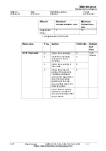
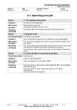
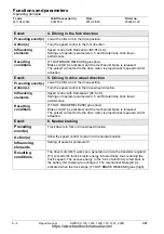
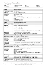
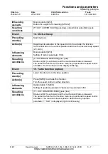
4110 Tiller arm

a

Check the mountings.

X

1:45 
minutes

b

Inspect the operating 
console for correct 
mounting

X

c

Check the mounting of 
the handle.

X

d

Check the force and 
locking of the gas strut.
The tiller arm should 
return to the top position 
both from the bottom 
position and from the 
lower position where the 
brake is applied.

X

Check that the braking 
function is activated in 
both upper and lower tiller 
arm positions.

Wheels

Standard 
measurements, mm

Minimum 
dimensions, 
mm

https://www.besttruckmanuals.com/

Содержание SWE100

Страница 1: ... BT Industries AB Repair manual en SWE100 120 120L 120S 140 140L 200D Applies from serial number 6061850 Order number 258946 120 Issued 2012 08 30 TP https www besttruckmanuals com ...

Страница 2: ...hydraulics Chapter 17 Tightening torques hydraulic unit added Chapter 23 Updated with new tool Table 21 4 Overflow pressure mast added Various minor corrections throughout entire document 2012 08 30 258946 XXX Chapter 5 Maintenance 5 3 Maintenance schedule updated 3180 brakes Chapter 6 Function and Parameters 6 5 5 Service parameters 204 206 added 6 5 6 Factory parameters 1024 added Chapter 8 Chas...

Страница 3: ...ameters 105 106 och 111 4 6 Programming PIN for resetting the truck 4 7 4 4 2 Adjusting the parameters for the battery and battery charger 4 7 4 4 3 Parameter 107 battery size 4 9 Free ventilated batteries 4 9 Verifying the parameter adjustment for free ventilated batteries Lead acid batteries 4 10 Verifying the parameter adjustment for valve controlled batteries Hawker Exide 4 10 4 5 Function and...

Страница 4: ...tibility matrix 7 27 7 6 5 Defective hydraulic functions 7 28 7 7 Built in test function 7 31 7 8 Digital input output status 7 32 7 8 1 Test function 9 Transistor regulator 7 32 7 8 2 Test function 10 Logic card 7 35 7 8 3 Test function 12 Expansion unit SEU option 7 36 7 9 Test function for the display 7 37 8 Chassis 0000 8 1 8 1 Support arm 0350 8 1 8 1 1 Support arm lift lateral adjustment 8 1...

Страница 5: ...le new model 15 4 15 5 3 Components of the tiller arm handle old model 15 6 15 5 4 Disassembly assembly of tiller arm handle 15 8 15 5 5 Replacing the horn button switch 15 11 15 5 6 Replacement of lift lower button 15 11 15 5 7 Replacing the button 15 12 15 5 8 Changing the position of the controls support arm lift fork lift 15 13 15 5 9 Replacing the safety reversal switch 15 14 16 Electrical co...

Страница 6: ...chain system 7120 18 4 18 3 1 Checking the chain setting 18 4 18 3 2 Chain inspection 18 4 Noise 18 4 Surface rust 18 4 Rusty links 18 4 Stiff links 18 4 Bolt rotation 18 5 Loose bolts 18 5 Outline wear 18 5 Stretching 18 6 Damage 18 7 Damaged discs 18 7 Damaged bolts 18 7 Dirty chain 18 7 18 3 3 Cleaning 18 7 18 3 4 Lubrication 18 8 18 4 Replacing the fork carriage 18 9 18 5 Replacement of the ma...

Страница 7: ...ultilock series 040 23 4 23 3 Molex connectors 23 4 23 4 Grease guns 23 5 23 5 Other tools 23 6 24 Oil and grease specification 24 1 25 Electrical components and wiring diagrams 25 1 25 1 Electrical components 25 1 25 2 Wiring diagram 25 5 25 2 1 List of symbols 25 5 25 2 2 General wiring diagram 25 6 25 2 3 Wiring diagram 25 7 26 Hydraulics chart 26 1 27 Instructions for disposal 27 1 27 1 Genera...

Страница 8: ...1 6 Repair manual SWE100 120 120L 120S 140 140L 200D BT Contents T code Valid from serial no Date Order no 841 842 843 6061850 2012 08 30 258946 120 https www besttruckmanuals com ...

Страница 9: ... schedule and a detailed description of the maintenance to be carried out Troubleshooting The troubleshooting chapter describes the error codes that are displayed when the truck is partially or completely out of service It also describes the cause of the problem and suggests remedies Service Actions This chapter describes the different parts of the truck e g the hydraulic system descriptions of co...

Страница 10: ...tic discharge Heed applicable ESD safety precautions Note Note means there is a risk of material loss or damage if the instructions are not followed It is also used to call for attention to various points 2 3 Pictograms 2 3 1 Screws Nuts Wherever possible pictograms have been used to describe certain work operations Pictograms are primarily used for operations that require loosening or tightening ...

Страница 11: ...ivities often involve kneeling or bending forward Try sitting on a toolbox for example to relieve the strain on your knees and back loose articles and jewellery may become trapped in the moving parts of the truck Never wear loose articles or jewellery while working on the truck use well maintained tools that are intended for the work being carried out store and transport old oil according to appli...

Страница 12: ... working on the electrical system always switch off the truck s power supply before opening the hoods to the drive assembly and the electrical system disconnect the battery when using electric welding equipment The welding current can enter and damage the battery always remove the battery plug when carrying out maintenance on the truck unless the instructions in this repair manual state otherwise ...

Страница 13: ...l balanced lift Ensure the area where you place the jack is clean and free of oil and grease Ensure there is no grease or oil on your hands or the jack lever Use the lever supplied with the jack If the lever is too short it will require more effort than is necessary If the lever is too long there is a risk that the jack will be overloaded Place supports as close to the raised part of the chassis a...

Страница 14: ...WE100 120 120L 120S 140 140L 200D BT General safety rules Safe lifting T code Valid from serial no Date Order no 841 842 843 6061850 2012 08 30 258946 120 Denna sida är avsiktligt lämnad tom https www besttruckmanuals com ...

Страница 15: ...he battery will be damaged and its lifetime reduced Always use protective equipment to protect the eyes face and skin when you are inspecting handling or filling batteries DANGER Battery acid causes burns If your skin or clothing comes into contact with battery acid rinse the area immediately with cold water If your face or eyes come into contact with battery acid rinse the area with cold water an...

Страница 16: ...ce is loosened if it has not been secured with an axle stand or other similar suspension gear of the right height Check the height of your suspension gear before loosening the lifting yoke 2 Check the electrolyte level in the battery This should normally be 10 15 mm above the cell plates 3 Connect the battery cables battery sleeve DANGER Always check that you have the right polarity when connectin...

Страница 17: ...implest is to use TruckCom where it clearly shows what to do See the separate manual for using TruckCom The other alternative is to use the truck s keypad Carry out the following to start the programming 1 Connect the CAN service key to socket X41 2 State code 341671 and press the ON button 3 Choose the programming code from the table below 4 Turn off the truck by pressing the OFF button Function ...

Страница 18: ... codes whose block number is activated The truck programme does not permit a login using the PIN code 0000 Note It is recommended that service personnel keep notes about activated blocks changed PIN codes and specially adjusted driver profiles Standard assignment for PIN codes Drive r profil e no 1 2 3 4 5 6 7 8 9 10 Note Stated as 0 Block 0 0001 0002 0003 0000 0000 0000 0000 0000 0000 0000 Block ...

Страница 19: ...ters Check that parameters are adjusted to desire values with regards to maximum speed driver parameter see chapter Functions and parameters acceleration driver parameter see chapter Functions and parameters internal braking driver parameter see chapter Functions and parameters Collision sensor option battery battery charger option Note When you check or adjust parameters remember to write down in...

Страница 20: ...lay and the driver s identity can also be read via the PIN code Other information is received via TruckCom where the collision levels and times can also be seen Collision sensor parameters 105 106 och 111 See the table below for information about the values that can be stated Note If you set the parameter value for the collision sensor at 0 zero this means that the collision sensor and the log fun...

Страница 21: ...0000 which must be changed to a chosen PIN code by a service technician Note The PIN code must not contain the same number combination as any of the preprogrammed PIN codes 4 4 2 Adjusting the parameters for the battery and battery charger The following parameters must be adjusted or checked on battery installation Note Even if the battery comes with the truck from the factory the parameters must ...

Страница 22: ...h 1 20 1 9 9 Large battery 13 Medium battery 17 Small battery For more information see text following the table See section 4 4 3 Parameter 107 battery size 109 service parameter Battery charger battery type 0 3 1 0 State battery type 0 No charge Standard type Error code is displayed if this parameter is set at 0 when there is a battery charger and factory parameter 1101 is set at 1 1 Lead acid ba...

Страница 23: ...s See the table below for the recommended parameter settings DANGER The battery s service life will be reduced if the value of parameter 107 is set to a value that is too high The standard adjustment of parameter 107 is set for normal handling of the truck Other applications may require a different adjustment of parameter 107 Check that the parameter adjustment is right using the instructions belo...

Страница 24: ...ed the parameter value can be increase by up to one unit Note Each change must be followed by renewed verification of the parameter setting Verifying the parameter adjustment for valve controlled batteries Hawker Exide 1 Charge the battery 2 Use the truck in its normal application until the battery indicator shows a discharged battery 0 on the display 3 Disconnect the battery from the truck and le...

Страница 25: ... switch Check function c Horn Check function d Steering Check function e Brake Check function f Emergency switch Check function g Hydraulic system Check all components h Drive unit Investigate possible noises and oil leaks j Wheel Investigate damage remove dirt etc k Chassis Investigate damage remove dirt etc m Battery cover and lock Check function n Battery Check acid and charging level o Fork ca...

Страница 26: ...100 120 120L 120S 140 140L 200D BT Installation Function and safety check T code Valid from serial no Date Order no 841 842 843 6061850 2012 08 30 258946 120 Denna sida är avsiktligt lämnad tom https www besttruckmanuals com ...

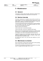
Страница 27: ...rs have been used when calculating the intervals Daytime 08 00 17 00 20 h week 2 shifts 06 00 14 00 14 00 22 00 40 h week 3 shifts 06 00 14 00 14 00 22 00 22 00 06 00 60 h week Make sure the truck undergoes regular maintenance at intervals of 750 operating hours The safety efficiency and expected service life of the truck depend on the service and maintenance the truck receives Following completed...

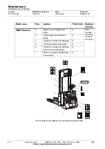
Страница 28: ...a Pos Action 750h 12m Estimat ed time 0000 Chassis a Inspect cover hinges and locks X 5 20 minutes including removal of covers b Check signs and adhesive labels X c Check for cracks and damage X d Check the mast fixing bolts X e Check for cracks and damage to the motor fixing points X f Secure the paper holder strap if necessary X a a b b b b b b b b b c d d e A B C D M PLATE A B C D E E F G Qmax ...

Страница 29: ...ly applies to trucks with support arm lift SWE120L SWE140L and SWE200D X c Check for cracks and damage to the push rods1 X d Check all shafts links and locking pins1 X Work area Pos Action 750h 12m Estimat ed time 0380 Fork carriage e Check for cracks and damage X 1 30 minutes f Check the rollers for looseness X g Check the load support Option X Inspect the fork stop screws SWE120S X Check that th...

Страница 30: ...lid from serial no Date Order no 841 842 843 6061850 2012 08 30 258946 120 Work area Pos Action 750h 12m Estimat ed time 0560 Platform and mountings a Check for cracks and damage X 1 30 minutes b Check the spring and that the platform returns to upright position X a b https www besttruckmanuals com ...

Страница 31: ...ormal noise in the drive motor bearings X 2550 Drive gear d Inspect for abnormal noise X e Check the mountings and play in the steering bearings X 3180 Brakes f Check for wear on the brake disc Minimum brake disc thickness 7 9 mm X g Check the gap of the parking brake when it is not applied Nominal brake gap 0 3 mm Minimum permitted gap 0 2 mm Maximum permitted gap 0 5 mm Measuring must be done ar...

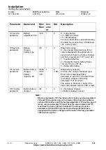
Страница 32: ...ion 750h 12m Estima ted time 3500 Wheels a Check for wear on the drive wheel X 2 minutes b Check the nuts X c Inspect castor wheel wear1 1 Not applicable for SWE120S X d Check for wear on support arm wheels X e Check whether the swivel wheel swings freely1 X Wheels Standard measurements mm Minimum dimensions mm Drive wheels 30 15 Castor wheel1 10 5 a b c d e https www besttruckmanuals com ...

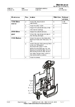
Страница 33: ...m a Check the mountings X 1 45 minutes b Inspect the operating console for correct mounting X c Check the mounting of the handle X d Check the force and locking of the gas strut The tiller arm should return to the top position both from the bottom position and from the lower position where the brake is applied X Check that the braking function is activated in both upper and lower tiller arm positi...

Страница 34: ...ors wiring harness including the battery cables cable insulation and verify that all cables can move freely X 4 30 minutes b Inspect the contactors for correct operation X c Check error code log operating times and all the segments on the display X d Clean and check that there is no play between the steering box and the heat dissipation plate X e Check and tighten the cable connections X f Check a...

Страница 35: ...Maintenance schedule BT Repair manual SWE100 120 120L 120S 140 140L 200D 5 9 Order no Date Valid from serial no T code 258946 120 2012 08 30 6061850 841 842 843 b a c d a e a e a e f https www besttruckmanuals com ...

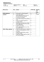
Страница 36: ...ding to illustration X c Check the mountings of the hydraulic unit X d Inspect the hydraulic system for possible leakage X e Change the oil and clean the oil tank Note Initially after 750 h 12 m then every 4500 h 36 m X f Clean the oil strainer Note Initially after 750 h 12 m then every 4500 h 36 m X 6600 Lifting cylinder g Inspect the lifting cylinder for leakage X h Inspect the lifting cylinder ...

Страница 37: ... Check that there is no looseness in the mast s mounting points X c Check for play between the mast beam and the inner runner s rollers X d Check the inner runner s side play X e Check for wear on lifting chains and sprockets See section 18 3 Main lift chain system 7120 500 h f Check the adjustment of the lifting chains See section 18 3 Main lift chain system 7120 500 h g Lubricate the inside surf...

Страница 38: ...100 120 120L 120S 140 140L 200D BT Maintenance Maintenance schedule T code Valid from serial no Date Order no 841 842 843 6061850 2012 08 30 258946 120 End of section a b b b b c d e e e e f g https www besttruckmanuals com ...

Страница 39: ...y a number Prior events Indicates events which must have taken place immediately before the current event in order for the latter to be performed correctly Action s An action that the operator must perform in order for an event to happen Influencing factors Conditions that must be fulfilled in order for an event to happen Certain parameter settings may also affect the outcome of the event Resultin...

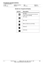
Страница 40: ... Valid from serial no Date Order no 841 842 843 6061850 2012 08 30 258946 120 Symbols on keypad and display Symbol Description ON button This button is used to start the truck and confirm entered settings OFF button Error code Battery charge as a percentage Parameter Hour meter https www besttruckmanuals com ...

Страница 41: ...N button on the keypad S223 Influencing elements The emergency stop S21 has not been activated T1 INP SUPPLY 24V DC high Resulting conditions The current lamp shines Main display shows the hour meter for 4 seconds and after this the battery charge as a percentage of full charge The mechanical brake remains applied Q1 T1 OUT BRAKE RELEASE high Event 3 Lower the tiller arm to the drive position Prec...

Страница 42: ... the speed control in the drive wheel direction Influencing elements Speed control with Hall sensor A5 S1 9 Settings of operator parameters 4 5 and 6 determine truck travel performance Resulting conditions T1 OUT BRAKE RELEASE goes low Brake coil Q1 is activated and the mechanical brake is released The pulsed current fed to the drive motor is proportional to speed control actuation Event 6 Neutral...

Страница 43: ...r down Influencing elements Sensor for tiller arm in drive position B60 Resulting conditions Sensor for tiller arm in drive position B60 deactivated T1 INP TILLER ARM IN DRIVE POS low When the tiller arm is completely raised or lowered maximum permitted brake reduction is applied for 200 ms or until the travel speed is lower than 0 8 m s After this the mechanical brake Q1 is applied T1 OUT BRAKE R...

Страница 44: ...ions T1 OUT PUMP CONTACTOR goes low The pump contactor Q25 closes the pump motor M3 starts Event 11 Fork lowering Preceding event s Start the truck or commence fork lifting Action s Press the fork lowering button A5 S20 Influencing elements Main contactor Q10 Fork lowering button A5 S20 Resulting conditions T1 OUT LOWER VALVE goes low proportional valve Q4 opens Event 12 Support arm lift SWE120L 1...

Страница 45: ...ting conditions T1 OUT BRAKE RELEASE goes low Brake coil Q1 is activated and the mechanical brake is released The pulsed current fed to the drive motor is proportional to speed control actuation SLO is shown on the display blinking Event 15 Turtle function option Preceding event s Lower the tiller arm to the drive position Action s Press S206 to activate this function Turn the speed control in eit...

Страница 46: ...priate PIN code Note Without pressing the ON button 4 Keep the horn button depressed until H is displayed then release the button The hour meter symbol lights Press the speed control repeatedly to cycle through the different hour meter values The current time value will be displayed a short while after this mode has been selected Hour recorder values Display Value 1 Key time Total time truck has b...

Страница 47: ...in a CAN service key however it is not possible to change the values Factory parameters Parameters pre set at the factory which in case of special requirements can be changed by a service technician As an example these parameters indicate the truck model and which controls to use for the hydraulic function The factory parameters cannot be changed with the CAN service key All parameters can be chan...

Страница 48: ... horn button when the display shows P The parameter symbol is lit continuously 2 Turn the speed control to scroll to the desired parameter Release the control when the display shows the correct parameter number 3 Press once on the horn button to change the value The parameter symbol starts blinking 4 Change the value by turning the speed control 5 Confirm the setting by pressing once more on the h...

Страница 49: ... ault Description 4 Acceleration 10 100 5 70 Determines the truck s acceleration capacity The lower the value of this parameter the longer time it takes for the truck to accelerate to top speed 5 Deceleration 10 100 5 90 Determines the braking force when the speed control is returned to neutral position The lower the value of this parameter the longer the time to reduce speed 6 Maximum speed 30 10...

Страница 50: ... operator profiles 1 and 4 10 are the default values Note When replacing the firmware the factory presettings of operator profiles 2 and 3 are lost In this case all operator profiles are assigned the same default values i e the default values of operator profiles 1 and 4 10 To regain the factory settings these values must be entered anew either manually or via a PC PDA Operator profile Parameter F...

Страница 51: ...et in parameter 110 Note For Hawker Evolution batteries only the battery sizes 134Ah 174Ah and 201Ah may be used Before any service parameter can be adjusted the CAN service key must be connected to the connector X41 Param eter Designation unit Min Max Incr eme nt Def ault Description 101 Serviceinterval hours 0 2000 50 0 Specifies a limit when the next service should take place Error code 2 003 i...

Страница 52: ...pact Be sure to set this parameter when installing the truck For more information see the Installation chapter 107 Battery setting Ah 1 20 1 9 9 Large battery 13 Medium battery 17 Small battery For more information see the text below the table 108 Calibrating 1 1 1 Calibration of proportional valve Automatically reset to zero after completed calibration See the chapter on hydraulics for complete i...

Страница 53: ...truck should brake when the speed control is turned fully in the opposite direction Note This value must not be set lower than the value of parameter 5 If it is lower error code 2 002 is shown at start up and the value is not changed 202 Creep speed 200 200 5 0 Determines the speed the truck will have when it reaches the value set for the first travel speed sensor 200 Low speed for the first speed...

Страница 54: ...on 30 150 5 90 Determines the start position of the proportional valve This parameter can be adjusted manually or can be set by using the calibration function parameter 108 1 304 EVP support arms lowering speed 50 220 5 130 Determines the lowering speed of the support arms This parameter can be adjusted manually or can be set by using the calibration function parameter 108 1 305 EVP slow lowering ...

Страница 55: ...eeds arise The user ID and time of parameter change are logged in the circuit board of the handle Param eter Designation unit Min Max Incr eme nt Def aul t Description 1001 Truck type 0 8 1 0 0 Unknown truck type 1 SWE100 2 SWE120 3 SWE140 4 SWE120L 5 SWE140L 6 SWE200D 7 SWE080L 8 SWE120S 1002 Non configurable options 0 3 1 1 3 different functions are accessible via parameter 1002 These functions ...

Страница 56: ...5 1 0 Requires SEU 1013 ConfOption Func3 0 13 1 0 Requires SEU 1014 ConfOption Func3Arg1 0 255 1 0 Requires SEU 1015 ConfOption Func3Arg2 0 255 1 0 Requires SEU 1016 ConfOption Func3Arg3 0 255 1 0 Requires SEU 1017 ConfOption Func3Arg4 0 255 1 0 Requires SEU 1018 ConfOption Func4 0 13 1 0 Requires SEU 1019 ConfOption Func4Arg1 0 255 1 0 Requires SEU 1020 ConfOption Func4Arg2 0 255 1 0 Requires SEU...

Страница 57: ...ed to the first hydraulic function and forward control connected to second hydraulic function 3 Both lifting and lowering controls are connected to the first hydraulic function There are no other hydraulic functions 4 The analogue lifting and lowering control is connected to the first hydraulic function while the front control is connected to the second hydraulic function 1024 Brake configuration ...

Страница 58: ...0 Repair manual SWE100 120 120L 120S 140 140L 200D BT Functions and parameters Parameters T code Valid from serial no Date Order no 841 842 843 6061850 2012 08 30 258946 120 https www besttruckmanuals com ...

Страница 59: ...A5 and the transistor regulator ACT T1 and the battery charger BCU A30 have the software from the same software package Download and install the latest software package in order to maintain full functionality Emergency travel mode If truck for some reason stops operating and remains immobile in an unsuitable place it is possible to active the emergency travel mode to move the truck out of the way ...

Страница 60: ...g Nej Följ instruktionerna i felsökningsschemat Ja Nej Samla så mycket information som möjligt om problemet Identifiera alla delar som kan orsaka problemet Använd vid behov kopplingsschema Eliminera osannolika fel Välj ut och prioritera de mest sannolika orsakerna När du lokaliserat felet se instruktioner i sektionen för åtgärder Var på arbetsplatsen uppstod problemet Vilka förhållanden utlöste pr...

Страница 61: ...llda till korrekt nivå Återskapa samma förutsättningar som gällde när problemet först uppstod Kör trucken på samma sätt som den kördes när problemet först uppstod Verifiera att problemet inte uppstår igen Låt föraren köra trucken Verifiera att problemet inte uppstår igen Genom återkoppling kan du bidra till en gemensam kunskapsdatabas Detta är viktigt för fortsatt förbättrad support till servicete...

Страница 62: ...ecent one Proceed as follows to display the error code log 1 Ensure that the battery is connected 2 Ensure that the truck is switched off Press the OFF button 3 Enter the appropriate PIN code Note Without pressing the ON button 4 Keep the horn button depressed until E is displayed then release it The error code symbol lights The most recent error is shown The display alternates between the error c...

Страница 63: ...m and other 3 The drive system 4 The hydraulic system 5 Not used 6 Not used 7 Not used 8 Option Error category Description 0 Proceed with caution This is primarily an information code that indicates that some of the truck functions have been reduced or do not operate 1 2 Minor error Lifting and lowering of the forks are disabled and the truck travel speed is reduced to safety speed 3 Not used 4 Cr...

Страница 64: ...load interrupted Transmission cable disconnected Restart the download in Emergency download mode 2 001 Transistor regulator stops all functions Emergency switch off has been actuated Check that the emergency switch off is not pressed cable 24 fuse F51 2 002 No event Truck can be operated as usual Some parameter values may be outside the pre set values The parameters will be reset to the default va...

Страница 65: ...up See section 15 5 4 Disassembly assembly of tiller arm handle If this does not help indicate the type of truck by entering factory parameter 1001 Truck type or see table 7 6 4 2 102 Safety speed raising and lowering the forks not working The set truck type does not support analogue lifting and lowering operations Check the settings of factory parameters 1001 Truck type and 1023 Controls for hydr...

Страница 66: ...Incorrect power supply to the Hall sensor Use TruckCom to check whether the Hall sensors are working 2 523 The main contactor is open Main contactor is not activated Check if the main contactor is working Open the main contactor Drive system 3 001 Travel disabled until the speed control is reset to the neutral position The speed control was not in the neutral position during start up Defective Hal...

Страница 67: ...ensor for the transistor regulator shows abnormal values Internal transistor regulator error Restart the truck If the error persists change the transistor regulator 3 081 The transistor regulator reduces current feed to 50 The motor temperature sensor shows abnormal values The sensor could be defective Check the cables 63 64 to the motor temperature sensor 3 101 Safety speed raising and lowering t...

Страница 68: ... 3 140 Horn disabled Safety speed The horn output is short circuited Check connections and wiring harness cable 50 the horn 3 501 The main contactor is open Faulty transistor regulator Check the transistor regulator factory parameter 1001 Truck type If the error persists change the transistor regulator 3 502 The main contactor is open The logic card in the tiller arm handle cannot download paramet...

Страница 69: ...ad of software in the mode Emergency download software Make sure that ICH A5 and ACT T1 have software from the same software package connections and wiring harness cables 119 and 120 transistor regulator T1 replace if needed If the error remains re install the transistor regulator T1 and replace the logic card A5 of the handle 3 511 The main contactor is open The logic card of the tiller arm handl...

Страница 70: ...annot send CAN data to the transistor regulator Check connections and wiring harness cables 119 and 120 the logic card in the tiller arm handle and replace it if necessary If the error continues change the transistor regulator 3 515 Transistor regulator stops all functions The transistor regulator has detected a CAN communication error Check connections and wiring harness cables 119 and 120 the lo...

Страница 71: ...in its own firmware or hardware Internal transistor regulator error Reprogram the truck both in the handle and the transistor regulator 3 524 Transistor regulator stops all functions The transistor regulator has detected an internal problem in its own firmware or hardware Internal transistor regulator error Reprogram the truck both in the handle and the transistor regulator 3 525 Transistor regula...

Страница 72: ...ator stops all functions The transistor regulator has detected an internal problem Internal transistor regulator error Check the software If the error persists change the transistor regulator 3 530 Transistor regulator stops all functions The transistor regulator has detected an internal problem Internal transistor regulator error Check the software If the error persists change the transistor regu...

Страница 73: ...tions and wiring harness the speed sensor and replace if needed 3 535 Transistor regulator stops all functions Incorrect checksum for the transistor regulator parameters Download the latest software to the handle and the transistor regulator 3 536 Transistor regulator stops all functions The transistor regulator current supply unit is outside the valid range Internal transistor regulator error Rep...

Страница 74: ...he transistor regulator output to the parking brake is short circuited Check connections and wiring harness the parking brake 3 542 Transistor regulator stops all functions One of the transistor regulator s circuits to the main contactor parking brake or lowering valve is short circuited to 24 V at start up Check connections and wiring harness main contactor parking brake the lowering valve 3 560 ...

Страница 75: ...nctions The main contactor is closed Check connections and wiring harness the main contactor 3 581 Transistor regulator stops all functions Main contactor open Check connections and wiring harness the main contactor the main fuse F1 3 582 Transistor regulator stops all functions The transistor regulator s output for power supply has the wrong voltage Check connections and wiring harness main conta...

Страница 76: ... Do not actuate the speed control when starting the truck Check the wiring in the handle the potentiometer If defective replace the potentiometer 4 102 Safety speed raising and lowering the forks not working The handle type does not match the setting of factory parameter 1023 Controls for hydraulic functions Check the setting of factory parameter 1023 and compare with the handle type on the truck ...

Страница 77: ...ns The transistor regulator output to the lowering valve is short circuited Internal short circuit in the transistor regulator Inspect the connections and wiring harness Disconnect the wiring to the lowering valve and try restarting the truck If the error remains replace the lowering valve or the transistor regulator 4 541 Transistor regulator stops all functions The transistor regulator output to...

Страница 78: ... event Truck can be operated as usual CAN communication problem with the battery charger at start up Inspect the connections and wiring harness Make sure that ICH A5 and BCU A30 have compatible software See section 7 1 General 8 011 No event Truck can be operated as usual The logic card in the tiller arm handle is not receiving CAN data from the battery charger Inspect the connections and wiring h...

Страница 79: ...he battery charger Replace the battery charger 8 028 No event Truck can be operated as usual The battery charger has exceeded the time limit for charging Check the battery 8 029 No event Truck can be operated as usual The battery charger is charging more than maximum capacity Check battery service parameter 110 8 030 No event Truck can be operated as usual Battery charger is installed in truck but...

Страница 80: ...ctions and wiring harness 8 114 Safety speed raising and lowering the forks not working CAN communication problem with Spider expansion unit 2 at start up Inspect the connections and wiring harness 8 115 Safety speed raising and lowering the forks not working CAN communication problem with Spider expansion unit 2 Inspect the connections and wiring harness 8 123 Safety speed raising and lowering th...

Страница 81: ...843 7 6 Troubleshooting chart The following section describes the type of errors that can occur together with a description of their cause The troubleshooting is grouped according to symptoms The truck cannot be driven The truck can be driven but only at reduced speed The truck can be driven but behaves abnormally Defective hydraulic functions https www besttruckmanuals com ...

Страница 82: ...gulator Mechanical brake cannot be released Brake If the gap is greater than 0 6 mm the brakes may be difficult to apply Sensor B60 Sensor in wrong position or cannot be influenced normally Defective sensor Break in sensor wiring Transistor regulator input T1 95 Transistor regulator output T1 90 Broken transistor regulator Corrosion Brake has seized due to corrosion Truck cannot travel after start...

Страница 83: ...Possible cause Speed always reduced Click 2 Creep function Click 2 Creep function activated Turtle function Turtle function activated Operator parameter 6 speed Operator parameter 6 has not been set to the maximum value Pulse transducer B11 Defective or disconnected pulse transducer B11 Motor cable connections One of the phases U V W is not connected Broken cable Mechanical brake Partially applied...

Страница 84: ...ation always reduced Driver parameter 4 Value setting low Reversing braking always reduced Service parameter 201 Value setting low Neutral braking always reduced Driver parameter 5 Value set too low The truck cannot be switched off Parameter 102 The Red off key on the keypad does not work Parameter 102 has been incorrectly set for the log in unit installed in the truck Speed always reduced Pulse s...

Страница 85: ...rix Make sure the correct software of the logic card A5 and the transistor regulator T1 have been installed in the truck by referring to the matrix below ACT was not replaced transistor regulator T1 ACT replaced transistor regulator T1 ICH was not replaced logic card A5 OK Warning 2 004 Use TruckCom to download new backup values Open TruckCom and select Copy configuration to secondary unit ACT ICH...

Страница 86: ...evel Clogged suction filter Defective or wrongly adjusted pressure limiting valve Defective hydraulic pump replace the hydraulic unit Pump motor M3 does not work Hydraulic unit fuse F3 125 A has blown replace fuse Fore more information see the table Pump motor M3 does not operate below Measure current and voltage through and across the pump motor M3 respectively Pump motor M3 voltage current norma...

Страница 87: ... The proportional valve Q4 for lowering the forks does not open on page 30 Solenoid valve voltage current normal No current or voltage through across the solenoid valve coil Voltage across solenoid valve coil but no current through the coil Forks can neither be raised nor lowered Defective fuse F50 7 5 A Replace the fuse Logic card A5 faulty Replace the logic card Defective transistor regulator T1...

Страница 88: ...r lowering the forks does not open Symptom Influencing elements Possible cause Remedy The proportional valve s Q4 current voltage is normal Mechanical fault in the proportional valve Q4 Replace the hydraulic unit No or low current voltage through across the proportional valve s coil Q4 Damage to the proportional valve s Q4 wiring harness or connections Check the wiring harness for interruptions or...

Страница 89: ...o choose Built in Test function Note All truck functions operate as normal in this mode Care should be taken when operating the truck and reading the display at the same time Mod e Flashing symbol Data shown in the display Normal value 1 Battery voltage V 2 Current across battery A 3 The set speed value that is sent to the transistor regulator Min 142 Max 142 4 Travel speed value from travel speed...

Страница 90: ...alue in each input output 3 and 4 The transistor regulator s set point Relating to what the software value should be A H Reference to segment One or more segments may be lit continuously at each position The indications can also be combined across several positions xxx in the table is the component designation nn in the table is the wiring number in the electrical wiring diagram 11 Maximum value r...

Страница 91: ...ke applied Tiller arm in drive position B60 INP TILLER ARM IN DRIVE POS D On Tiller arm in drive position Off Tiller arm in one of the end positions E Not assigned Support arm in lower position B62 INP SUPPORT ARM IN LOWEST POS F On Down Off Up Fork under mast sensor 1 B63 INP MAST SWITCH 1 G On Down Off Up H Not assigned A Not assigned B Not assigned C Not assigned D Not assigned E Not assigned F...

Страница 92: ...ELEASE D On Brake released Off Brake applied E Not assigned Pump motor M3 active F On Active Off Not active Proportional valve Q4 G On Affected Off Not affected H Not assigned Pump contactor Q25 OUT PUMP CONTACTOR1 1 Only applies to SWE100 A On Contactor closed Off Contactor open Fork valve Q22 OUT FORK VALVE2 2 Applies only to SWE120L 140L and 200D B Not assigned Support arm valve Q23 OUT SUPPORT...

Страница 93: ...ressed Rear fork lift button A5 S21 F On Button depressed Rear fork lowering button A5 S22 G On Button depressed Sound signal control S18 H On Button depressed Outermost option button right side S116 A On Button depressed Centre option button right side S115 B On Button depressed Innermost option button right side S114 C On Button depressed Outermost option button left side S113 D On Button depres...

Страница 94: ...function 12 Expansion unit SEU option Function Pos 1 Pos 2 Pos 3 Pos 4 Digital input 1 A Digital input 2 B Digital input 3 C Digital input 4 D Digital input 5 E Digital input 6 F Digital input 7 G Digital input 8 H Digital output 1 A Digital output 2 B Digital output 3 C Digital output 4 D E Not assigned F Not assigned G Not assigned H Not assigned A B C D E F G H https www besttruckmanuals com ...

Страница 95: ...tself can be tested to verify all segments of the display function correctly Proceed as follows to the test the display 1 Ensure that the battery is connected 2 Ensure that the truck is switched off Press the OFF button 3 Enter the appropriate PIN code Note Without pressing the ON button 4 Keep the horn button depressed until d is displayed then release it All segments and symbol icons must flash ...

Страница 96: ...air manual SWE100 120 120L 120S 140 140L 200D BT Troubleshooting Test function for the display T code Valid from serial no Date Order no 841 842 843 6061850 2012 08 30 258946 120 https www besttruckmanuals com ...

Страница 97: ...hassis 0000 8 1 Support arm 0350 8 1 1 Support arm lift lateral adjustment 1 Loosen the locking nut 2 Adjust the lateral guides using the adjustment screw b There are four adjustment screws 3 Adjust the lateral guides so that there is no play but so that the lowering does not jam 4 Lock the adjustment screws position with the locking nut b a https www besttruckmanuals com ...

Страница 98: ...sure plate and the support arm link roller must be between the minimum value of 0 4 and the maximum of 2 0 1 Check the gap A precondition for checking the gap is that the roller is fitted and that they are in the lowered position 2 Loosen the cylinder a if the gap is incorrect 6 mm Allen 3 Place a suitable number of shims 7501642 under the cylinder a 4 Tighten the cylinder 5 Check that the gap is ...

Страница 99: ...t the ground 1 Remove the covers and the battery door The top cover is secured with Velcro tape Be careful when detaching the cover Use of a suitable tool is recommended 2 Lift out the battery 3 Disconnect the cables to the drive motor and the pump motor and also the wiring harness 4 Disconnect the cable duct 5 Unfasten the battery connector and the battery cable bracket 6 Install the threaded M16...

Страница 100: ... 8 Change the upper stop screws for M8 x 120 washers are not needed 9 Remove and discard the screws to the upper bracket 10 Remove the lower screws 11 Compress the spring assembly using the threaded bar until the lips are clear 12 Unload the springs by prying up the bracket using the threaded bar Note Check that the bushings do not get stuck or become damaged during reassembly https www besttruckm...

Страница 101: ...ply a load on the platform and loosen the upper dampening stop together with the spring cover plate 2 Disassemble the platform from the truck by loosening the four bolts 3 Put the platform on the floor behind the truck with the spring facing you and placing the other edge under the truck s foot guard 4 Loosen all 8 screws securing the bracket which the spring clamp is pushing against https www bes...

Страница 102: ...Order no 841 842 843 6061850 2012 08 30 258946 120 Note Pay utmost attention when working with tensioned springs 5 Relieve the spring using a crowbar or a large screwdriver and carefully remove the bracket 6 Pull out the axle and replace the part s that should be replaced 7 Install in reverse order https www besttruckmanuals com ...

Страница 103: ...alid from serial no T code 258946 120 2012 08 30 6061850 841 842 843 9 Electric drive motor 1700 9 1 Components Pos Description A Speed sensor B Connection motor cables C Motor SWE120L 140 140L 200D 1 5kW C Motor SWE100 120 120S 1 0kW D Temperature sensor E Dust shield D A B C E https www besttruckmanuals com ...

Страница 104: ...he truck 1 Remove the covers The top cover is secured with Velcro tape Be careful when detaching the cover Use of a suitable tool is recommended 2 Cut off the cable ties of the cable duct on the transistor regulator side and disconnect cable connectors X5 and X60 3 Loosen the operating console s mounting screws a and remove the operating console and tiller arm 4 Remove the brake s cable connection...

Страница 105: ...ver the drive gear to prevent loose items from falling into the drive gear after the drive motor has been removed Install the motor in the reverse order See section 9 3 Tightening torques Drive motor Note When installing the motor it is very important that the motor is aligned so that the grooves in the motor and the motor bracket are exactly opposite each other before the mounting screws are fitt...

Страница 106: ... SWE100 120 120L 120S 140 140L 200D BT Electric drive motor 1700 Disassemble the motor from the truck T code Valid from serial no Date Order no 841 842 843 6061850 2012 08 30 258946 120 a https www besttruckmanuals com ...

Страница 107: ...an the area and make sure all surfaces are dry 4 Apply plastic steel by pushing out a string that is half the length of the curing agent compared to the putty then carefully mix the two be careful not to mix a larger amount than will be used in 5 minutes 5 Apply a layer of plastic steel at least 4 mm thick and make sure the repaired surface has an overlap of at least 2 cm 6 Secure the steel plasti...

Страница 108: ...ularly inspect the motor and motor compartment for build up of dust oil and other contaminants Dirty and or greasy components should be cleaned with a rag moistened with solvent Use a rag of lint free cloth material Do not use too much solvent as it could penetrate into the motor parts After cleaning dry the components thoroughly The easiest way is by heating Note Windings and insulation must not ...

Страница 109: ... 1700 Cleaning BT Repair manual SWE100 120 120L 120S 140 140L 200D 9 7 Order no Date Valid from serial no T code 258946 120 2012 08 30 6061850 841 842 843 Denna sida är avsiktligt lämnad tom https www besttruckmanuals com ...

Страница 110: ...8 Repair manual SWE100 120 120L 120S 140 140L 200D BT Electric drive motor 1700 Cleaning T code Valid from serial no Date Order no 841 842 843 6061850 2012 08 30 258946 120 https www besttruckmanuals com ...

Страница 111: ...e 258946 120 2012 08 30 6061850 841 842 843 10 Drive gear 2550 10 1 General The drive gear is combined with the motor and brake assembly in a complete drive unit The complete overhaul of the drive gear must be performed by the supplier 10 2 Components Pos Description a Drive gear b Screw b a https www besttruckmanuals com ...

Страница 112: ...d 2 Cut off the cable ties of the cable duct on the transistor regulator side and disconnect cable connectors X5 and X60 3 Unscrew the retaining screws of the steering console and remove the steering console and the tiller arm 4 Disassemble the speed sensor and disconnect the cable connections Q1 and B1 5 Disconnect the motor cables and unscrew the retaining screws of the motor 6 Lift the motor ou...

Страница 113: ...0 Lift the motor bracket using the threaded rod until the drive wheel is lifted approx 4 mm from the floor 11 Unscrew the retaining screws of the gear box 12 Lift carefully approx 125 mm lay the gear down on the floor 13 Lift a further 100 mm a total of 225 mm and pull it out to the rear edge Install in reverse order Please note the risk of crushing when installing the unit Steps 12 13 https www b...

Страница 114: ...duct on the transistor regulator side and disconnect cable connectors X5 and X60 5 Unscrew the retaining screws of the steering console and remove the steering console and the tiller arm 6 Disassemble the speed sensor and disconnect the cable connections Q1 and B1 7 Disconnect the motor cables and unscrew the retaining screws of the motor 8 Lift the motor out of the truck 9 Insert a plug in the ho...

Страница 115: ... T code 258946 120 2012 08 30 6061850 841 842 843 11 Brakes 3180 In normal use the brake should not require any maintenance 11 1 Components Pos no Description A Circlip B Complete brake assembly C Screw D Key E Hub F Brake disc G Flange H Dust shield I Cable bushing B C E D F G H I A https www besttruckmanuals com ...

Страница 116: ...20 11 2 Releasing the brake Note The brakes should only be released when the truck needs to be moved in connection with service and repair work The brakes on the truck can be released manually by screwing two screws M5 into the holes A The screws must be 30 35 mm long Note Remember to remove the screws before operating the truck again A A https www besttruckmanuals com ...

Страница 117: ...r no Date Valid from serial no T code 258946 120 2012 08 30 6061850 841 842 843 11 3 Installing the dust shield Applicable to serial number up to and including 6140925 Step 1 Step 2 Step 3 Steps 4 5 and 6 Gap minimum 0 2 Step 7 Step 8 Step 9 Steps 10 and 11 Step 12 T 23 https www besttruckmanuals com ...

Страница 118: ...with compressed air these may be carefully scraped away Measure the air gap between the magnet housing of the brake unit and the movable pressure disc Measuring must be done around the entire pressure disc both on the inside and the outside Note It is extremely important that an air gap of min 0 2 mm is maintained all around the brake If the prescribed measurement cannot be maintained the brake mu...

Страница 119: ...rder no Date Valid from serial no T code 258946 120 2012 08 30 6061850 841 842 843 11 4 Installing the dust shield Applicable to serial number starting with 6140927 Step 1 Step 2 Step 3 Steps 4 5 and 6 Gap minimum 0 2 Step 7 Steps 8 Steps 9 and 10 T 5 Nm Step 12 T 23 https www besttruckmanuals com ...

Страница 120: ...cessary until a 0 2 mm feeler gauge can be inserted If there are particles that cannot be cleared away with compressed air these may be carefully scraped away Measure the air gap between the magnet housing of the brake unit and the movable pressure disc Measuring must be done around the entire pressure disc both on the inside and the outside Note It is extremely important that an air gap of min 0 ...

Страница 121: ...wheel 3530 12 1 Replacing the drive wheel Method DANGER Risk of crushing since a poorly supported truck could fall 1 Pull out the battery 2 Lift up the truck about 100 mm and support it with trestles 3 Turn the drive wheel diagonally from one of the sides 4 Unscrew the 5 nuts and remove them along with the washers 5 Lift out the wheel Step 1 Step 2 Step 4 Step 5 https www besttruckmanuals com ...

Страница 122: ...6061850 2012 08 30 258946 120 Installing the drive wheel on the truck 1 Fit the drive wheel 2 Fasten the screws and washers 3 Tighten the screws crosswise tightening torque 81 19 Nm 4 Remove the trestles and lower the truck to the ground 5 Connect the battery Step 1 Step 2 Step 3 Step 4 Step 5 n s mm Step 3 s 17 n 5 Mv 81Nm https www besttruckmanuals com ...

Страница 123: ...serial no T code 258946 120 2012 08 30 6061850 841 842 843 13 Castor wheels 3540 This chapter does not apply to SWE120S 13 1 Components Pos Description Pos Description A Circlip H Screw B Washer I Spacer C Screw J Spacer D Bracket K Bearing E Washer L Guard F Bearing M Nut G Circlip https www besttruckmanuals com ...

Страница 124: ... 2 Replacing the castor wheel Method DANGER Risk of crushing since a poorly supported truck could fall 1 Support the truck in a secure manner 2 Disconnect the truck battery 3 Unscrew the castor wheel 4 Refit the castor wheel and its four fastening screws and washers 5 Connect the battery 6 Remove the support trestles Step 1 Step 2 Steps 3 and 4 Step 6 Step 5 https www besttruckmanuals com ...

Страница 125: ...L 120S 140 140L 200D 14 1 Order no Date Valid from serial no T code 258946 120 2012 08 30 6061850 841 842 843 14 Support arm wheel 3550 Pos Name a Screw b Bracket c Bogie wheel d Single wheel e Axle f Locking ring a b c d e f https www besttruckmanuals com ...

Страница 126: ...nual SWE100 120 120L 120S 140 140L 200D BT Support arm wheel 3550 T code Valid from serial no Date Order no 841 842 843 6061850 2012 08 30 258946 120 Denna sida är avsiktligt lämnad tom https www besttruckmanuals com ...

Страница 127: ...mponents O Pos Description Pos Description A Tiller arm M Indicator sleeve B Rubber buffer N Plate C Cylindrical bolt O Yoke D Gas strut P Cable clamp E Circlip Q Screw F Rubber buffer R Yoke G Bushing S Screw H Threaded insert T6 Cover I Spring pin U Cover J Holder V Cable clamp K Safety sensor B60 W Mounting screw for cable clip L Shaft A B C D E F G H I J K L M N O P Q R S T U V w https www bes...

Страница 128: ...e hole in the control console Note Do not attempt to pry it out with a screwdriver 5 Cut off the cable ties of the cable duct on the transistor regulator side and disconnect cable connectors X5 and X60 Assemble in reverse order 15 3 Replacing the gas strut 1 Remove the cover T 2 Remove the cable clamp mounting screw W 3 Remove the adjusting screw Q 4 Remove the locking mechanism E from the locking...

Страница 129: ...ot drop and damages the wiring harness 7 Remove the cable clip mounting screw W 8 Remove the sensor s mounting screw W 9 Remove connector B60 from the sensor K 10 Remove the sensor 15 4 2 Installation 1 Fit the sensor K 2 Fit connector B60 to the sensor 3 Put some Loctite on the threads of the sensor mounting screw S or replace the screw Screw in the screw 4 Fit the cable clip mounting screw W Not...

Страница 130: ...ring system 4000 T code Valid from serial no Date Order no 841 842 843 6061850 2012 08 30 258946 120 9 Check the safety sensor for correct operation 15 5 Electrical steering system 4000 15 5 1 Tiller arm handle C4110 15 5 2 Components of the tiller arm handle https www besttruckmanuals com ...

Страница 131: ...em 4000 BT Repair manual SWE100 120 120L 120S 140 140L 200D 15 5 Order no Date Valid from serial no T code 258946 120 2012 08 30 6061850 841 842 843 new model A B Y C D E G H I J K L R S T K L M P O N U V X Q F https www besttruckmanuals com ...

Страница 132: ...er arm 4000 Electrical steering system 4000 T code Valid from serial no Date Order no 841 842 843 6061850 2012 08 30 258946 120 15 5 3 Components of the tiller arm handle old model A B C A D E F G H I J M K L K L N O P Q R S T U V X https www besttruckmanuals com ...

Страница 133: ...escription Pos Description A Symbol board M Speed control travel direction selector B Push button N Display C Push button O Cable clip D Safety reversing push button P Cable clip E Spring Q Cover F Logic card R Plug G Seal S Cover transparent plastic H Spring T6 Seal I Cover U Handle J Seal V Cover K Horn button X Wiring harness L Signal switch Y Butterfly switch https www besttruckmanuals com ...

Страница 134: ...L 200D BT Tiller arm 4000 Electrical steering system 4000 T code Valid from serial no Date Order no 841 842 843 6061850 2012 08 30 258946 120 15 5 4 Disassembly assembly of tiller arm handle Step 1 Step 2 Step 3 Step 4 https www besttruckmanuals com ...

Страница 135: ...stem 4000 BT Repair manual SWE100 120 120L 120S 140 140L 200D 15 9 Order no Date Valid from serial no T code 258946 120 2012 08 30 6061850 841 842 843 B B Step 5 Step 6 Step 10 Step 13 Step 14 Step 15 Step 16 https www besttruckmanuals com ...

Страница 136: ...peed control assembly from falling down 6 Lift off the speed control assembly 7 If the logic card is to be replaced disconnect its connectors and lift out the logic card Assembly 8 Fit the new logic card in place and connect it 9 Check the cable connection on the logic card and that the contacts are correctly connected 10 Fit the speed control assembly in position Hook the ends of the spring aroun...

Страница 137: ...racket 5 Fit the new switch and connect the cable to the logic board 6 Align the button with the catch and secure it by hand 7 Assemble the tiller arm handle See section 15 5 4 Disassembly assembly of tiller arm handle 15 5 6 Replacement of lift lower button 1 Disassemble the tiller arm handle See section 15 5 4 Disassembly assembly of tiller arm handle 2 Remove the button by placing a screwdriver...

Страница 138: ...alid from serial no Date Order no 841 842 843 6061850 2012 08 30 258946 120 15 5 7 Replacing the button 1 Press out the button laterally with the fingers 2 Place a screwdriver as illustrated and carefully pry out the button 3 Unscrew the button holder and arm Assemble in reverse order https www besttruckmanuals com ...

Страница 139: ...5 5 8 Changing the position of the controls support arm lift fork lift 1 Pry off the lift control buttons using a thin screwdriver and switch the positions with the rear buttons 2 Make sure the lips catch when the new buttons are inserted 3 Connect a PDA or PC and use TruckCom to change parameter 1023 to 2 4 Start the truck and make sure the change is correct https www besttruckmanuals com ...

Страница 140: ...m serial no Date Order no 841 842 843 6061850 2012 08 30 258946 120 15 5 9 Replacing the safety reversal switch 1 Remove the keypad by loosening the screw and disconnect the connector 2 Loosen the screws securing the upper part of the tiller arm 3 Disconnect the CAN connector 1 2 5 mm 4 4 mm https www besttruckmanuals com ...

Страница 141: ...S 140 140L 200D 15 15 Order no Date Valid from serial no T code 258946 120 2012 08 30 6061850 841 842 843 4 Loosen the screws until the switch brackets come loose 5 Remove the button by unhooking the locks on both sides 6 Assemble in reverse order 3 3 mm https www besttruckmanuals com ...

Страница 142: ...air manual SWE100 120 120L 120S 140 140L 200D BT Tiller arm 4000 Electrical steering system 4000 T code Valid from serial no Date Order no 841 842 843 6061850 2012 08 30 258946 120 https www besttruckmanuals com ...

Страница 143: ...g the wiring harness Proceed as follows when replacing the wire harness 1 When separating X connectors press in the connector lock A to the female part B and pull upwards 2 Disconnect the female part B of the connector from the male part D 3 Then remove the male part D by pulling it downwards Pos Description A Connector lock B Connector female part C Bracket D Connector male part X21 X5 X60 A B C ...

Страница 144: ...1 842 843 6061850 2012 08 30 258946 120 The bracket C remains on the connector panel 16 1 1 Replacing the transistor regulator cables Keep the following in mind if it becomes necessary to disconnect the connector A of the transistor regulator First press down on the bracket clamp B Then lift up the connector lever C A B C https www besttruckmanuals com ...

Страница 145: ...ect the connectors A from the connector bracket 4 Loosen the screws D and fold away the connector bracket 5 Disconnect all cables and connectors from the transistor regulator 6 Loosen the mounting nuts B of the back plate 7 Remove the transistor regulator Take out the back plate starting from the upper edge then turn it in the truck s drive wheel direction to remove it from the truck 8 Unscrew the...

Страница 146: ...al components Replacing the transistor regulator T code Valid from serial no Date Order no 841 842 843 6061850 2012 08 30 258946 120 1 Connect TruckCom 2 Select Copy truck configuration 3 Select Copy configuration to secondary unit ACT https www besttruckmanuals com ...

Страница 147: ...sures before you beging working with the truck s hydraulic system Release the system s pressure gradually Use paper or a stiff piece of cardboard when checking for possible leakage Do not use hands Take care as the oil in the transmission and hydraulic systems may be hot DANGER If you come into contact with hot transmission and hydraulic oil there is a risk of burns Allow the truck to cool down be...

Страница 148: ...ding to ISO4406 1999 or alternatively 16 13 according to ISO4406 1987 Components can be blown clean using dry filtered air when this is the only practically feasible cleaning method 17 2 2 Packaging After cleaning all openings must be sealed using protective plugs Connection faces must be protected against damage caused by handling and against the ingress of dirt Completely dry components can be p...

Страница 149: ...being carried out on hydraulic systems observe a level of cleanliness such that contaminants do not get into the system Machining by chip removal must never take place at the same or close to a workplace at which work is carried out on hydraulic systems The service technician is to ensure that components being used are thoroughly deburred and cleaned Closures for pipe ends or other openings must n...

Страница 150: ...r M3 h Hydraulic fork connection b Magnetic valve support arm selection Q23 1 1 Only applies to SWE120L SWE140L and SWE200D i Pressure limit valve c Magnetic valve fork selection Q22 1 k Max oil level d Proportional valve lowering Q4 m Filling cap e Tank suitable oil volume 5 l n Pump motor cable connection f Screw o Pump motor cable connection g Hydraulic connection support arm a d c h g f i k m ...

Страница 151: ...eeding Cylinders with bleeding valve 1 Loosen all bleeding screws 2 revolutions 2 Lift slowly at a constant rate until the forks begin to rise 30 40 cm 3 Close the bleeding screws 4 Lower the forks and continue to press the lowering button for 10 15 s 5 Top up with oil 6 Lift the forks to max 7 Lower and check the oil level Cylinders without bleeding valve 1 Lift slowly at a constant rate until th...

Страница 152: ...7 4 Hydraulic connections 6230 17 4 1 Quick change connector Assembling the quick change connector 1 Place the assembly stop 1 on the male fitting and make sure that the dismantling ring 2 runs freely in the groove 2 Push the male fitting into the female fitting until the assembly stop makes contact with the female fitting 3 The coupling is now made and locked https www besttruckmanuals com ...

Страница 153: ...30 6061850 841 842 843 Dismantling the quick change connector 1 Remove the assembly stop with the aid of a screwdriver or similar tool 2 Push the male fitting all the way into the female fitting 3 Pull the male fitting out of the female fitting 4 Refit the assembly stop on the male fitting 5 Place protective plugs on the valve and hose https www besttruckmanuals com ...

Страница 154: ...ay pending one of the two signal buttons being pressed The calibration starts when one of the signal buttons is pressed The lowering valve then opens slowly As soon as the operator feels the lowering movement of the forks the sig nal button must be released Wait until the display end appears on the display and then restart the truck Service parameter 108 resets auto matically after a calibration h...

Страница 155: ...e truck must be able to handle the rated load on the forks Place a rated load on the forks and verify that the truck is able to lift it If the truck cannot lift the rated load 1 Prise off the sealing cap a around the pressure limiting valve using a screwdriver 2 Loosen the protective cover b 17 mm by turning it anti clockwise Remove the protective cover and washer inside it 3 Loosen the lock nut c...

Страница 156: ...ift the rated load add a further 100 kg onto the forks Verify that the truck cannot lift the load If the truck is able to lift 100 kg more than its rated load 1 Prise off the sealing cap a around the pressure limiting valve using a screwdriver 2 Loosen the protective cover b 17 mm by turning it anti clockwise Remove the protective cover and washer inside it 3 Loosen the lock nut c 17 mm by turning...

Страница 157: ...841 842 843 17 7 Disassembling the hydraulic unit Before commencing any work on the hydraulic unit make sure the forks have been fully lowered 1 Disconnect the hydraulic hose See section 17 4 1 Quick change connector 2 Undo the motor cables using a spanner 3 Disconnect electrical connection to the lowering valve n s mm Step 1 Step 2 Step 3 s 13 mm n 2off https www besttruckmanuals com ...

Страница 158: ...5 Loosen the clamp in order to detach the tank from the motor and lift the motor and valve block away from the tank 6 Remove and clean the strainer then reattach it in the correct position 7 Change the oil and clean the tank 8 Reassemble everything in reverse order See section 17 8 Hydraulic unit tightening torques NOTE Take care of the hydraulic unit seals when refitting it Step 4 Step 5 Step 6 n...

Страница 159: ...der no Date Valid from serial no T code 258946 120 2012 08 30 6061850 841 842 843 17 8 Hydraulic unit tightening torques The hydraulic unit tightening torques are depicted in the picture below 10 mm 10 2 Nm 13 mm 8 5 0 5 0 5 Nm 24 mm 45 5 Nm 5 0 8 0 8 Nm 24 mm 45 5 Nm 7 mm 4 0 5 0 5 Nm https www besttruckmanuals com ...

Страница 160: ...20L 120S 140 140L 200D BT Hydraulic system 6000 Hydraulic unit tightening torques T code Valid from serial no Date Order no 841 842 843 6061850 2012 08 30 258946 120 This page is intentionally left blank https www besttruckmanuals com ...

Страница 161: ... 1 Order no Date Valid from serial no T code 258946 120 2012 08 30 6061850 841 842 843 18 Lift mast 7000 18 1 Main mast 7100 18 1 1 Components Pos Description Tightening torque a Upper mast fixing points 189 8 Nm b Lower mast fixing points 83 4 Nm a b a b https www besttruckmanuals com ...

Страница 162: ...he maintenance chart the mast mounting bolts 8 should only be visually inspected and not re tightened on inspection If the mast needs to be replaced or if the bolts have come loose then be sure to use new bolts and washers The tightening torque should be according to the torque table Lubrication Lubricating the beam 1 The inside of the beam flanges are lubricated with Q8 Rembrandt EP2 https www be...

Страница 163: ... 258946 120 2012 08 30 6061850 841 842 843 18 2 Fork carriage 7420 18 2 1 Maintenance Check that the play in the fork carriage is not excessive Adjust with shims a if needed There are rollers with different diameters c to compensate for any wear on the guide rails Pos Description a Shims b Roller a b c https www besttruckmanuals com ...

Страница 164: ... and stretching Wear to the bolts and disc holes is caused by stretching The chains are also affected by the environment in which they are used Noise If there has been insufficient lubrication there will be metallic friction on the chain and this will result in noise The chain must be replaced Surface rust Surface rust is easy to recognise as the chain will be reddish brown Deep seated rust has ge...

Страница 165: ...fault is easy to see when comparing with a new chain The chain must be replaced Loose bolts If a bolt is loose it will protrude from the side of the chain and this is due to a stiff link or bolt rotation The chain must be replaced Outline wear P Pitch H2 Nominal disc height H3 Minimum disc height A new lifting chain has a specific nominal disc height defined as H2 in the figure As the truck is use...

Страница 166: ...in that runs over the chain roller The amount of stretch may at the most be 2 on the most worn section of the chain The measurement is best made over 300 1000 mm of chain The nominal and maximum permitted chain lengths for lifting chains are stated in the table below Wear to the bolts and around the holes on the discs are one reason why the chain stretches The chain should be replaced if stretchin...

Страница 167: ... must be replaced Damaged bolts It can be difficult to discover whether a bolt has broken It can appear as bolt rotation and or that the outer disc is loose The chain must be replaced Dirty chain If a chain is very dirty replacement is recommended first and foremost It can also be removed and cleaned as set out in the chapter Cleaning 18 3 3 Cleaning If a chain is very dirty replacement is recomme...

Страница 168: ...e sprayed with lubricant Note the entire chain must be lubricated even the fastening bolts It is particularly important that the part of the chain that runs over the chain wheel is well lubricated The lubricate must comply with the viscosity demands at respective temperatures as set out in the table below The following lubricants are recommended Similar products from other manufacturers may be use...

Страница 169: ...9 Order no Date Valid from serial no T code 258946 120 2012 08 30 6061850 841 842 843 18 4 Replacing the fork carriage 1 Lift the fork carriage with an overhead crane or with another truck to take the load off the chain 2 Remove the chain bolt 3 Lower the fork carriage https www besttruckmanuals com ...

Страница 170: ...40L 200D BT Lift mast 7000 Replacing the fork carriage T code Valid from serial no Date Order no 841 842 843 6061850 2012 08 30 258946 120 4 Lift the inner guides 5 Remove the fork carriage 6 Install in reverse order https www besttruckmanuals com ...

Страница 171: ...20 2012 08 30 6061850 841 842 843 18 5 Replacement of the mast We use a Duplex Hilo mast in this example 1 Start by disconnecting the fork carriage according to the example above 2 Disconnect all connectors to the lift height switches 3 Remove the spiral hose 4 Disconnect the main hydraulic hose from the T connector https www besttruckmanuals com ...

Страница 172: ...d from serial no Date Order no 841 842 843 6061850 2012 08 30 258946 120 5 Connect a hose plug in the hose to stop the oil flow 6 Lift out the battery 7 Lower the mast and secure it in both lifting points with an overhead crane or using another truck See section 23 5 Other tools https www besttruckmanuals com ...

Страница 173: ... 120S 140 140L 200D 18 13 Order no Date Valid from serial no T code 258946 120 2012 08 30 6061850 841 842 843 8 Remove the lower finger protectors and the bracket for the hydraulic hose on the cylinder 9 Remove the four bolts holding the mast https www besttruckmanuals com ...

Страница 174: ...ift mast 7000 Replacement of the mast T code Valid from serial no Date Order no 841 842 843 6061850 2012 08 30 258946 120 10 Make sure that the mast is freed and lift it past the guide lugs 11 Attach the new mast in reverse order https www besttruckmanuals com ...

Страница 175: ... Valid from serial no T code 258946 120 2012 08 30 6061850 841 842 843 18 6 Adjusting the mast The angle of the mast must be checked after replacement Make sure that the truck is standing on a level surface when checking Fit shims according to the instructions below if needed https www besttruckmanuals com ...

Страница 176: ... BT Lift mast 7000 Adjusting the mast T code Valid from serial no Date Order no 841 842 843 6061850 2012 08 30 258946 120 Tighten the screws that hold the mast See section 18 1 1 Components with the correct tightening torque https www besttruckmanuals com ...

Страница 177: ...logic which means that a defective SEU can be replaced without the replacement affecting any truck functions The SEU is used for modification of the truck to meet special customer requirements The figure above shows how the SEU is used to allow a greater number of functions to be controlled via the CAN bus SEU has a 42 pin multipin contact that manages all inputs outputs CAN and power supply signa...

Страница 178: ...42 843 6061850 2012 08 30 258946 120 19 2 TLS Truck log system See the separate manual that is included with the truck log system 19 3 ID unit See the separate manual that is supplied with the software 19 4 Toyota Wireless Information System T W I S See the separate manual that is supplied with the software https www besttruckmanuals com ...

Страница 179: ...battery charger mounting nuts A with a maximum of 1 6 Nm The battery charger is set for the battery if the truck is delivered from the factory with a battery installed If the truck is delivered without a battery the client or a technician must set the correct parameter according to type and size of the battery 19 5 1 Technical data Designation SMCO 24 30 Dimensions mm 240x111x77 Weight kg 1 7 Ambi...

Страница 180: ... is shown on the display Main charging During the charging process lines appear sequentially from left to right The battery symbol and the OFF button blink Equalising charging Four lines at the left in the display light continuously while four lines on the right appear sequentially The battery symbol and the OFF button blink Charging completed The battery capacity value and unit Ah appear alternat...

Страница 181: ...20 2012 08 30 6061850 841 842 843 20 Appendices 20 1 General In the chapter Appendices you can quickly find the following information technical data general tightening torques tools oil and grease specifications electrical components and wiring diagrams hydraulics chart instructions for disposal https www besttruckmanuals com ...

Страница 182: ...manual SWE100 120 120L 120S 140 140L 200D BT Appendices General T code Valid from serial no Date Order no 841 842 843 6061850 2012 08 30 258946 120 Denna sida är avsiktligt lämnad tom https www besttruckmanuals com ...

Страница 183: ...otor Type Iskra AML7108 Iskra AML7109 Output kW 1 0 1 5 Duty cycle S2 60 min Weight kg 9 10 5 Brake Type Warner PK10 Braking force Nm 15 Output W 51 13 Resistance coil Ω 10 5 12 0 Nominal play in actuated position mm 0 3 Minimum thickness of brake disc mm 7 9 Thickness of a new brake disc mm 8 2 Transmission gear Type Kordel Genius 5 72 02 1 Gear ratio 30 204 Oil volume litres 0 8 Oil type 100 syn...

Страница 184: ...oad kg 235 285 285 Axle pressure at rated load kg 1185 1445 1640 Castor wheel mm 85 Axle pressure without load kg 230 250 200 Axle pressure at rated load kg 280 290 245 Hydraulic system Output kW 2 2 Duty cycle Minimum carbon brush length mm Minimum commutator thickness diameter mm Pressure at rated load bar Overflow pressure bar Pump flow litres minute Tank volume litres Oil type Normal temperatu...

Страница 185: ...load m s 6 0 1 7 With rated load km h With rated load m s 6 0 1 7 Lift lowering speed Lift without load m s 0 28 0 28 0 25 Lift with rated load m s 0 14 0 12 0 11 Lowering without load m s 0 38 0 38 0 38 Lowering with rated load m s 0 38 0 38 0 37 Gradient capabillity With rated load 8 8 8 Measurement Short Medium Long 1831 1888 1938 1906 1956 1901 1951 Lift height 3300 4500 4755 Weight Truck with...

Страница 186: ...ive motor Type Iskra AML7109 Output kW 1 5 Duty cycle S2 60 min Weight kg 10 5 Brake Type Warner PK10 Braking force Nm 15 Output W 51 13 Resistance coil Ω 10 5 12 0 Nominal play in actuated position mm 0 3 Minimum thickness of brake disc mm 7 9 Thickness of a new brake disc mm 8 2 Transmission gear Type Kordel Genius 5 72 02 1 Gear ratio 30 204 Oil volume litres 0 8 Oil type 100 synthetic API GL 5...

Страница 187: ...load kg 265 265 215 Axle pressure at rated load kg 1345 1525 1155 Castor wheel mm 85 Axle pressure without load kg 220 220 100 Axle pressure at rated load kg 340 360 360 Hydraulic system Output kW 2 2 Duty cycle Minimum carbon brush length mm Minimum commutator thickness diameter mm Pressure at rated load bar Overflow pressure bar Pump flow litres minute Tank volume litres Oil type Normal temperat...

Страница 188: ...load km h Without load m s 6 0 1 7 With rated load km h With rated load m s 6 0 1 7 Lift lowering speed Lift without load m s 0 25 Lift with rated load m s 0 12 0 11 0 12 Lowering without load m s 0 28 Lowering with rated load m s 0 39 0 38 0 39 Gradient capabillity With rated load 9 8 9 Measurement Short Medium Long 1910 1960 Lift height 3300 3255 2100 Weight Truck without battery Medium 715 715 ...

Страница 189: ...ML7108 Output kW 1 0 Duty cycle S2 60 min Weight kg 9 Brake Type Warner PK10 Braking force Nm 15 Output W 51 13 Resistance coil Ω 10 5 12 0 Nominal play in actuated position mm 0 3 Minimum thickness of brake disc mm 7 9 Thickness of a new brake disc mm 8 2 Transmission gear Type Kordel Genius 5 72 02 1 Gear ratio 30 204 Oil volume litres 0 8 Oil type 100 synthetic API GL 5 SAE 75W 90 https www bes...

Страница 190: ... without load kg 340 Axle pressure at rated load kg 1580 Castor wheel mm Axle pressure without load kg Axle pressure at rated load kg Hydraulic system Output kW 2 2 Duty cycle Minimum carbon brush length mm Minimum commutator thickness diameter mm Pressure at rated load bar Overflow pressure bar Pump flow litres minute Tank volume litres Oil type Normal temperature ISO VG32 ISO 6743 4 category HM ...

Страница 191: ...iving speeds Without load km h Without load m s 6 0 1 7 With rated load km h With rated load m s 6 0 1 7 Lift lowering speed Lift without load m s 0 21 Lift with rated load m s 0 11 Lowering without load m s 0 24 Lowering with rated load m s 0 33 Gradient capabillity With rated load 8 Measurement Short Medium Long 1946 1996 Lift height 4755 Weight Truck without battery Medium 795 Model SWE120S htt...

Страница 192: ...rom the graph for the hydraulic unit Recommended overflow pressure Simplex 1000 kg 140 Bar 7 1 165 Bar Simplex 1 200kg 165 Bar 6 5 190 Bar Tele 1000 kg 145 Bar 7 0 170 Bar Tele 1 200kg 170 Bar 6 4 195 Bar Tele ClearView 1000 kg 150 Bar 6 8 175 Bar Tele ClearView 1 200 kg 175 Bar 6 3 200 Bar Tele ClearView 1 400 kg 200 Bar 5 9 225 Bar Duplex HiLo 1200 kg 150 Bar 6 8 170 Bar Duplex HiLo 1 400 kg 170...

Страница 193: ...t torque value for galvanised bolts Do not tighten more than the values set out in the tables otherwise the bolts may be destroyed 22 2 Galvanised non oiled bolts 22 3 Untreated oiled bolts Tightening torque Nm Strength class 8 8 10 9 12 9 M3 1 1 1 6 2 0 M4 2 8 3 8 4 7 M5 5 5 7 7 9 3 M6 9 5 13 16 M8 23 32 38 M10 45 62 76 M12 78 109 130 M14 123 174 208 M16 189 266 320 M20 370 519 623 M24 638 898 10...

Страница 194: ...20 120L 120S 140 140L 200D BT General tightening torque Untreated oiled bolts T code Valid from serial no Date Order no 841 842 843 6061850 2012 08 30 258946 120 Denna sida är avsiktligt lämnad tom https www besttruckmanuals com ...

Страница 195: ...6061850 841 842 843 23 Tools 23 1 MQS connectors Tools Number Use 257841 MQS Basic toolbox The box contains 1 x pliers including tools 25 x splice sleeves 0 5 1 5 mm2 2x complete 2 3 4 6 8 and 12 pin contacts male and female with prewired cables and splicing sleeves Used to replace damaged contacts on the truck https www besttruckmanuals com ...

Страница 196: ... 2 0 5 mm2 200 x SWS sleeves 0 2 0 5 mm2 400 x SWS sleeves 0 5 0 75 mm2 100 x Clean body sleeves 0 5 0 75 mm2 200 x SWS pins 0 2 0 5 mm2 400 x SWS pins 0 5 0 75 mm2 1200 x sealings 200 x blind plugs 257843 MQS complete toolbox Contains 4 pliers including tools MQS SWS 0 25 0 5 mm2 MQS SWS 0 5 0 75 mm2 MQS Std Clean body 0 25 0 5 mm2 MQS Std Clean body 0 5 0 75 mm2 Puller for 2 3 4 6 8 and 12 pin m...

Страница 197: ...r 4 8 5 8 6 3 mm JPT Junior Power Timer 2 8 mm MPT Micro Power Timer 1 5 mm Figure Number Use 151080 PT Removal tool for pins sleeves 213296 JPT Removal tool for pins sleeves 213298 MPT Removal tool for pins sleeves 1 163787 JPT 2 163788 JPT 1 213336 MPT 2 213337 MPT Crimping tool for sleeves 1 213336 JPT 2 213549 JPT Crimping tool for pins For 0 5 2 5 mm2 1 2 1 2 https www besttruckmanuals com ...

Страница 198: ...er no 841 842 843 6061850 2012 08 30 258946 120 23 2 1 AMP connectors Multilock series 040 23 3 Molex connectors Figure Number Use 213130 Pin removal tool 213129 Crimping tool for pins Figure Number Use 156937 Crimping tool for pins sleeves 156936 Crimping tool for pins sleeves 1 8 9 16 https www besttruckmanuals com ...

Страница 199: ...ith straight pressure tube and nozzle 755142 Two hand grease gun with angled pressure tube and nozzle 755152 Two hand grease gun with hose and nozzle 755145 755146 755147 Lubricating hose 450 mm Lubricating hose 750 mm Lubricating hose 1500 mm 202154PM Pointed nozzle for grease guns to apply grease in recessed nipples Fits grease guns with hose and pressure tube Length 125 mm 755140 Nozzle for tal...

Страница 200: ...der no 841 842 843 6061850 2012 08 30 258946 120 23 5 Other tools Figure Number Use 156263 Service key CAN 1 7521083 2 163973 Service instrument CASTOR USB for programming 08 13022 Drive gear puller Threaded bar M16x500mm 3x M16 nuts and one washer V11 1666 Lifting tools Masts 1 2 https www besttruckmanuals com ...

Страница 201: ... below Chains Grease Grafloscon A G1 Klüber Gear rim Grease 755701 040 Castor wheel Grease S213366 Q8 Rubens WB Mast Hydraulic oil Ambient temperature Viscosity class Specification 0 C VG 27 5 ISO 6743 4 category HV DIN 51524 part 3 HVLP 0 C VG 32 ISO 6743 4 category HM DIN 51524 part 2 HLP Chain grease Ambient temperature Viscosity class Recommended products 40 C 30 C VG 15 Klüberoil 4UH 1 15 Klü...

Страница 202: ...l SWE100 120 120L 120S 140 140L 200D BT Oil and grease specification T code Valid from serial no Date Order no 841 842 843 6061850 2012 08 30 258946 120 Denna sida är avsiktligt lämnad tom https www besttruckmanuals com ...

Страница 203: ...k lift control A5 S20 Hall sensor Fork lowering control A5 S21 Hall sensor Support arm lift control A5 S22 Hall sensor Support arm lower control A30 Battery charger On board battery charger Option B1 Temperature sensor Drive motor temperature sensor B11 Pulse converter Speed sensor B60 Inductive switch Mechanical application of brakes B62 Inductive switch Support arms lowered position B63 Inductiv...

Страница 204: ...actor Contactor pump motor S18 Switch Horn button S21 Switch Emergency stop switch S97 Switch Warning lamp P5 Option S206 Switch Turtle function Option S111 Switch Option button Option S113 Switch Option button Option S114 Switch Option button Option S115 Switch Option button Option S116 Switch Option button Option S223 Keypad Smart card Log in with PIN code S224 Controls Sensi lift Option T1 Tran...

Страница 205: ...0L 120S 140 140L 200D 25 3 Order no Date Valid from serial no T code 258946 120 2012 08 30 6061850 841 842 843 A5 A5 S10 18 A5 S1 9 A5 S17 A5 S20 A5 S19 A5 S21 A5 S22 1 9 10 18 P6 S223 S113 S206 S111 S18 1 A5 S20 A5 S19 A5 S17 A5 S21 A5 S22 S18 2 S114 S116 S115 X41 https www besttruckmanuals com ...

Страница 206: ...0L 200D BT Electrical components and wiring diagrams Electrical components T code Valid from serial no Date Order no 841 842 843 6061850 2012 08 30 258946 120 S21 X1 G1 F1 F50 F51 F52 B90 X40 A30 Q10 Q25 T1 T7 T8 X21 https www besttruckmanuals com ...

Страница 207: ...l 2 List of symbols Symbol Description Symbol Description Truck battery Emergency switch off NC Fuse Switch pressure weight operated Horn Sensor inductive NO Motor a c 1 1 AC Alternating Current Sensor inductive NC Contactor Variable resistance potentiometer Brake coil normally applied Push switch NO Coil for hydraulic magnetic valve Multi pin connect Pressure sensor analogue NO Normally open NC N...

Страница 208: ...CONTACTOR 106 OUT PUMP CONTACTOR 107 DRIVE MOTOR PUMP MOTOR FORK VALVE 98 SUPPORT ARM VALVE 110 BRAKE RELEASE 90 PROP LOWER VALVE 108 24V 82 SIGNAL HORN 112 5V SPEED SENSOR 85 CAN HIGH LOW 99 100 0V DC X3 24V DC X3 CAN HIGH X3 CAN LOW X3 X3 24V DC X3 0V DC X3 X3 CAN HIGH LOW X1 1 HORN 2 X4 1 HORN 1 X4 2 X1 2 X2 1 2 TURTLE X2 1 3 TURTLE X8 1 5V DC X8 2 FORK LIFT LOWER X8 3 OUT 0V DC X12 X11 3 4 CAN...

Страница 209: ...CHARGE 84 INP B OUT MAIN CONTACTOR 106 G1 F50 7 5A Q10 1 2 1 2 F51 7 5A S21 1 2 OUT P 2D2 1D1 M3 PUMP MOTOR OUT U OUT V OUT W DRIVE MOTOR 40 Sh 2 40 1 21 1 Sh 3 30 Sh 2 24 Sh 3 6 6 2 3 4 20 31 5 20 Sh 4 B11 OUT NEGATIVE SPEED THERMAL SENSOR 105 INP THERMAL SENSOR 92 INP CH B SPEED SENSOR 103 INP CH A SPEED SENSOR 104 OUT 5V SPEED SENSOR 85 TEMP DRIVE MOTOR 60 61 62 63 64 M1 B1 X21 X21 21 WH 24 BN ...

Страница 210: ...ACTOR 106 G1 F50 7 5A Q10 1 2 1 2 F51 7 5A S21 1 2 OUT PUMP CONTACTOR 107 A1 1D1 A2 2D2 M3 PUMP MOTOR OUT U OUT V OUT W DRIVE MOTOR 40 Sh 3 40 1 21 1 Sh 3 Q25 1 2 1 2 30 Sh 2 24 Sh 2 6 6 2 3 4 20 31 34 20 Sh 4 B11 OUT NEGATIVE SPEED THERMAL SENSOR 105 INP THERMAL SENSOR 92 INP CH B SPEED SENSOR 103 INP CH A SPEED SENSOR 104 OUT 5V SPEED SENSOR 85 TEMP DRIVE MOTOR 60 61 62 63 64 10 F1 125A M1 B1 X2...

Страница 211: ...986 119 RD Sh 4 120 WH Sh 4 30 Sh 1 24 Sh 1 3 Q4 1 2 INP CAN LOW 100 INP CAN HIGH 99 120 WH 119 RD 83 INP 24V HIGH SIDE DRIVER MOTOR CONTROLLER T1 OUT PROP VALVE 108 OUT BRAKE RELEASE 90 Q1 1 2 OUT SUPPORT ARM VALVE 110 Q23 1 2 Q22 1 2 OUT FORK VALVE 98 OUT SIGNAL HORN 112 OUT 24V HIGH SIDE DRIVER 82 32 33 30 24 80 81 50 ONLY STACKER WITH SUPPORT ARM LIFT X20 X20 X20 X20 P4 IN 1 2 https www besttr...

Страница 212: ...1 2 3 40 Sh 1 4 86 INP MAST SWITCH 1 MOTRO CONTROLLER T1 INP MAST SWITCH 2 101 INP SUPPORT ARM IN LOWEST POS 94 B62 1 2 3 70 71 72 74 24 Sh 2 IF B62 NOT FITTED IF B64 NOT FITTED IF B63 NOT FITTED X20 X20 X20 X20 X65 X65 X65 X20 X20 X20 EXTERNAL EQUIPMENT X63 X63 X63 X63 X63 X63 X20 X20 NOTE EXTERNAL EQUIPMENT SHALL NOT BE ELECTRICAL CONNECTED TO THE TRUCK FRAME INP SUPPORT ARM AT TOP POS 87 B65 1 ...

Страница 213: ...CAN SERVICE CONNECTOR 4 3 120 119 120 WH Sh 2 7 20 Sh 1 9 X41 1 2 40 Sh 3 7 119 RD Sh 2 7 20 40 X3 CAN LOW ELECTRONIC CARD TILLER ARM A5 CAN HIGH X3 INP 0V DC X3 INP 24V DC X3 120 20 40 119 OUT 24V DC X3 CAN HIGH X3 CAN LOW X3 OUT 0V DC X3 A5 3 A5 7 A5 2 A5 6 A5 5 A5 1 A5 8 A5 4 X5 X5 X5 X5 20 40 119 120 FORK LIFT LOWER OUT 0V DC X8 4 INP A_IN X8 2 OUT 5V DC X8 1 OG RD BN BK VT GY WH PK https www ...

Страница 214: ...1850 2012 08 30 258946 120 5 11 PROD F 236986 S18 1 1 2 OPTION S113 1 2 S18 2 1 2 X1 6 X1 5 X1 4 X1 3 X1 2 P6 DISPLAY X1 1 P6 8 8 DISPLAY 8 8 INP HORN 1 X4 1 TURTLE X2 1 3 TURTLE X2 1 2 OUT 0V DC HORN 2 X1 2 INP HORN 2 X1 1 OUT OV DC HORN 1 X4 2 X12 1 5V DC ELECTRONIC CARD TILLER ARM A5 0V DC X12 6 LCLK X12 5 ENABLE X12 4 SCK X12 3 SI X12 2 https www besttruckmanuals com ...

Страница 215: ...alid from serial no T code 258946 120 2012 08 30 6061850 841 842 843 6 11 PROD F 236986 SMART CARD S223 KEY BOARD SMART CARD 8 9 7 0 I 4 1 5 6 2 3 0 X11 7 0V DC X11 10 LED_RED X11 9 LED_GREEN X11 8 X11 1 1 4 7 ELECTRONIC CARD TILLER ARM A5 7 8 9 X11 6 4 5 6 X11 5 1 2 3 X11 4 3 6 9 X11 3 2 5 8 0 X11 2 https www besttruckmanuals com ...

Страница 216: ...er no 841 842 843 6061850 2012 08 30 258946 120 7 11 PROD F 236986 ONBOARD CHARGER 40 Sh 4 8 BLACK 1 Sh 3 8 RED OPTION OUT NEGATIVE CHARGER VOLTAGE MAINS EARTH MAINS VAC MAINS VAC BLACK OUT POSITIVE CHARGER VOLTAGE BCU A30 RED INP CAN LOW 4 INP CAN HIGH 3 120 WH Sh 4 9 119 RD Sh 4 9 X40 X40 MAINS CONNECTOR 120 WH 119 RD https www besttruckmanuals com ...

Страница 217: ... 140 140L 200D 25 15 Order no Date Valid from serial no T code 258946 120 2012 08 30 6061850 841 842 843 8 11 PROD F 236986 INP 24VDC DC DC CONVERTER T7 T8 INP 0VDC OUT 12VDC 24VDC OUT 0VDC 25 40 26 41 X23 DC DC CONVERTER OPTION T7 24V 12V T8 24V 24V X21 X21 26 41 https www besttruckmanuals com ...

Страница 218: ... wiring diagrams Wiring diagram T code Valid from serial no Date Order no 841 842 843 6061850 2012 08 30 258946 120 9 11 PROD F 236986 1 INP 24V DC SHOCK SENSOR B90 INP 0V DC 2 CAN HIGH 3 CAN LOW 4 20 40 119 RD 120 WH SHOCK SENSOR OPTION X40 X40 X40 X40 https www besttruckmanuals com ...

Страница 219: ...0S 140 140L 200D 25 17 Order no Date Valid from serial no T code 258946 120 2012 08 30 6061850 841 842 843 10 11 PROD F 236986 1 INP 24V DC DHU K110 CAN HIGH 2 CAN LOW 3 INP 0V DC 8 20 119 RD 120 WH 40 DATA HANDLING UNIT DHU OPTION INP ANTENNA T20 X40 X40 X40 X40 https www besttruckmanuals com ...

Страница 220: ...BT Electrical components and wiring diagrams Wiring diagram T code Valid from serial no Date Order no 841 842 843 6061850 2012 08 30 258946 120 End of section 11 11 PROD F 236986 OPTION WARNING LIGHT X40 X40 P5 3 1 S97 1 2 220 https www besttruckmanuals com ...

Страница 221: ...Lift cylinder support arm1 1 Only applies to SWE120L SWE140L and SWE200D h Tank b Magnetic valve fork selection Q22 1 i Filter c Magnetic valve support arm selection Q23 1 k Filter d Proportional valve lowering Q4 m Air filter e Non return valve n Flow regulator valve f Pressure limit valve max 230 Bar o Lift cylinder forks g Pump p Hose fracture valve a b c d e f g h i k m n o p https www besttru...

Страница 222: ... manual SWE100 120 120L 120S 140 140L 200D BT Hydraulics chart T code Valid from serial no Date Order no 841 842 843 6061850 2012 08 30 258946 120 Denna sida är avsiktligt lämnad tom https www besttruckmanuals com ...

Страница 223: ...per sorting category of the materials used in the various truck components To achieve optimum sorting all components should be disassembled to a level corresponding to the sorting categories 27 2 Marking of plastics 27 2 1 General marking of products and packaging Markings on plastics consist of three arrows a number and usually also a designation of the plastic material used The picture shows the...

Страница 224: ... PP Abbreviations ABS acrylonitrile butadiene styrene HDPE High Density Polyethylene LDPE Low Density Polyethylene PA Polyamide PA6 Amide resin 6 PA66 Amide resin 66 PBT Polybutylene terephtalate PC Polycarbonate PET Polyethylene terephtalate PMMA Plexiglas POM Polyoxymethylene Polyformaldehyde PP Polypropylene PUR Polyurethane Marking examples Products made from a single substance ABS acrylonitri...

Страница 225: ...umulators used in hydraulic systems 27 3 1 Gas struts WARNING Gas struts have extremely high internal pressure To prevent injury always follow the instructions of the manufacturer Wear safety goggles when disassembling struts To allow the gas to escape only open and disassemble gas struts as prescribed by the manufacturer An example of how to perform this is given for Stabilus Lift O Mat Inter sto...

Страница 226: ...s to the manufacturer Component Category Comment Chassis Iron steel Inspection covers sheet metal Iron steel Handle ABS Inspection covers plastic Plastic Sort according to the material marking Forks and frames Iron steel Operator s platforms Iron steel including any gas dampers Mats cushions combustible Be sure to depressurise dampers Roofs and overhead guards Iron steel Side gates and operator pr...

Страница 227: ...to depressurise dampers Electrical system Logic cards transistor regulators Expansion unit SEU contactors Electronic components Cables Hazardous waste Small batteries Hazardous waste Fluorescent tubes Hazardous waste Because of the chemical content in fluorescent tubes do not destroy them Obsolete fluorescent tubes must be packaged and transported according to local regulations Masts Mast beams ro...

Страница 228: ... 120 120L 120S 140 140L 200D BT Instructions for disposal Sorting categories T code Valid from serial no Date Order no 841 842 843 6061850 2012 08 30 258946 120 Denna sida är avsiktligt lämnad tom https www besttruckmanuals com ...

Страница 229: ...https www besttruckmanuals com ...

Страница 230: ... BT SE 595 81 Mjölby Sweden www toyota forklifts eu https www besttruckmanuals com ...

Отзывы: