35
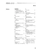
Index
Symbols
2-Channel Sub-Woofer
Operation.
See
Setting up
2-Way 2 Channel Operation.
See
Setting up
3-Way Mono Operation.
See
Setting
up
A
Active Crossovers
6
B
Balanced Input.
See
Input Connec-
tions
BSS Crossovers
9
C
Constant Directivity.
See
Equalising
CD Horns
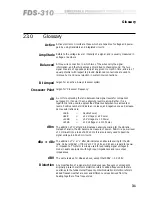
Contents
3
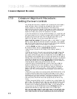
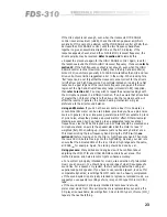
Crossover Alignment
22
CROSSOVER MODE
SELECTOR.
See
Setting up
Crossover Points
19
Crossovers
6
E
Equalising CD Horns
20
F
Front Panel
9
Full range Output
21
Fuses.
See
Mains Connection
G
Getting to know the FDS-310
9
Glossary
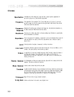
31
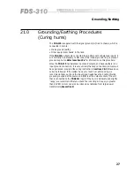
Grounding.
See
Mains Connection
Grounding/Earthing
27, 28
I
Input Connections
14
Installation
12
'Invisible' slopes.
See
Linkwitz-Riley
L
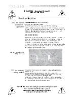
LED indicators
24
M
Mains Connection
13
Monaural Sub-Woofer Operation 20
Mute switch
27
O
Output Connections
15
Output Polarity Reversal
28
P
Passive Crossovers.
See
Section 2
Peak.
See
LED indicators
Polarity switch
28
Power ON.
See
Mains Connection
R
Rack space.
See
Installation
Rear Panel.
See
Getting to know the
FDS-310
Rolloff
7
S
Setting up
16
Signal Present.
See
LED indicators
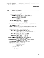
Specifications
33
Sub-Low/Sub-Bass.
See
2-Channel
Sub-Woofer Operation
Symmetrical radiation patterns.
See
Linkwitz-Riley filters
T
Troubleshooting
29
U
Unbalanced Input.
See
Input Connec-
tions
Unit dimensions.
See
Installation
Using an SPL meter.
See
Crossover
Alignment
Using R.T.A..
See
Crossover Align-
ment
Index
Содержание FDS 310
Страница 1: ...1 FDS 310 User Manual ...
Страница 10: ...1 0 Getting to know the FDS 310 Fig 6 1 Front Panel Fig 6 2 Rear Panel ...
Страница 11: ...11 All numbers in bubbles refer to Section numbers ...
Страница 37: ...37 User Notes ...
Страница 38: ...3 8 User Notes ...
Страница 39: ...39 User Notes ...
Страница 40: ...4 0 User Notes ...


