background image

27

21.0

Grounding/Earthing Procedures
(Curing hums)

The 

FDS-310

 is supplied with the signal ground (0V) tied to chassis, which is

connected in turn to:

• Mains ground (earth).
• Other equipment chassis' in the rack.

If the 

FDS-310

 outputs are connected to amplifiers with unbalanced inputs, it

will normally be necessary to disconnect the internal ground link, to prevent
ground-loop hums. 

Refer to section 22.4

 for information on this procedure:

Since the 

FDS-310

 has balanced inputs and outputs, and because there is no

input ground connection, it is very unlikely that any connection problem will
be experienced, 

provided the wiring instruction in 

sections 9 & 10

 have been

correctly followed.

 If the system has a very loud hum and buzzing, we

recommend that you check the input signal leads have their cable shields
properly grounded at the source end (that is at the output socket of the unit
that is connected to the 

FDS-310

s input). If the hum is moderate and slightly

'raspy', we recommend that you check the incoming AC supply is greater
than 90V RMS. Hum can also be induced by radiation from large power
transformers (

See section 8

).

Grounding/Earthing

Содержание FDS 310

Страница 1: ...1 FDS 310 User Manual ...

Страница 2: ...ssis via a capacitor to prevent ground loops whilst ensuring good EMC compatibility V 2 0 JMK 9 August 1996 We have written this manual with the aim of helping installers sound engineers and musicians to get to grips with the FDS 310 and obtain its maximum capability If you are new to BSS products we recommend that you begin at the start of the manual If however you are already familiar with the i...

Страница 3: ... Connections 14 9 1 Using Jack Plugs 14 9 2 Using XLR Plugs 14 10 0 Output Connections 15 10 1 Using Phone Plugs 15 10 2 Using XLR Plugs 15 11 0 Connection and Setup 16 11 1 Selecting 2 Way 2 Channel Operation 16 11 2 Selecting 3 Way Mono Operation 17 11 3 2 Channel Sub Woofer Operation 18 13 0 Unusual Crossover Points for 3 way systems only 19 12 0 Monaural Sub Woofer Operation for stereo 2 way s...

Страница 4: ...ut Polarity reversal option 25 20 0 Troubleshooting 26 21 0 Grounding Earthing Procedures Curing hums 27 22 0 Service Section 28 22 1 2 Channel Sub Woofer Operation 28 22 2 Mono Low Linking switch 28 22 3 Activating Equalisation 29 22 4 Eliminating Hum 30 22 5 Polarity Switching 30 23 0 Glossary 31 24 0 Specifications 33 25 0 Warranty Information 34 Index 35 User Notes 37 Spare Parts Information ...

Страница 5: ...ve units work best when they are driven over a limited band of frequencies for example Low Mid and High Any crossover aims to provide the division of the audio band necessary so each drive unit receives only the frequencies it is designed to handle In a high power high performance sound system the crossover should also reject unsuitable frequencies to avoid damage and poor quality sound Fig 1 1 St...

Страница 6: ... the same job as a passive crossover but with more precision flexibility efficiency and quality Fig 2 1 Active and Passive Crossovers Some advantages of active crossovers are Crossover frequencies can be more readily altered to suit different driver horn combinations The level balance between the 2 or 3 frequency bands brought on by differences in driver and amplifier sensitivity can be readily tr...

Страница 7: ...e slopes in excess of 12dB OCT are rarely achieved and power rolloff is 4 times less rapid per octave If one frequency range is driven into clip drive units and horns in other frequency ranges are protected from damage and distortion is kept to a minimum Direct connection of drive units to the power amplifier cut out loss of damping factor normally inevitable thanks to the appreciable resistance o...

Страница 8: ...of frequencies around the crossover point which is where the units from two adjacent frequency ranges are contributing near equal amounts of sound pressure More predictable sound dispersion By providing in phase summation at the crossover point s the Linkwitz Riley alignment provides for more coherent sound dispersion it provides on axis symmetrical radiation patterns See Figure 4 2 Invisible slop...

Страница 9: ... calibrated LEVEL CONTROL accommodates wide variations in the sensitivity of adjacent frequency bands A POLARITY switch enables each bands polarity or absolute phase to be reversed or inverted Additional optional internal settings are confirmed by panel LEDs Every FDS 310 is manufactured to the highest professional standards with a robust steel case high quality circuit boards ICs and high quality...

Страница 10: ...1 0 Getting to know the FDS 310 Fig 6 1 Front Panel Fig 6 2 Rear Panel ...

Страница 11: ...11 All numbers in bubbles refer to Section numbers ...

Страница 12: ...ar and or sides to lessen the stress on the front mounting flange The necessary support can generally be bought ready built as a rack tray As with any low level signal processing electronics it is best to avoid mounting the unit next to a strong source of magnetic radiation for example a high power amplifier to help keep residual noise levels in the system to a minimum Installation 44 mm 1 73 ins ...

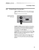
Страница 13: ...roper control over the system grounding To lift the signal ground 0V refer to section 21 AC Power fusing The incoming line passes through an anti surge T fuse accessible from the rear panel If the fuse blows without good reason refer to section 20 Always replace with an identical 20mm x 5mm T fuse rated at 200mA or 250mA for 230V or 115V settings respectively for continued protection from equipmen...

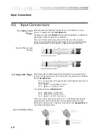
Страница 14: ...2 XLR Plug Wiring Each female XLR receptable accepts both balanced and unbalanced signal sources For balanced sources the incoming XLR plug should be connected as follows See Figure 9 2 Pin 1 No connection it is good practice to terminate the drain wire of the shield here Pin 2 Signal out of phase or COLD Pin 3 Signal in phase or HOT For unbalanced sources See figure 9 2 Pin 1 Leave open or link t...

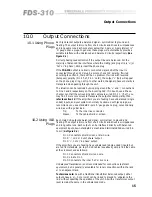
Страница 15: ...and floating The output is immune from short circuits and drives low impedances and long cable runs Each socket accepts either 2 pole or 3 pole stereo A gauge phone plugs In general these plugs will automatically provide a suitable interface with unbalanced and balanced circuits respectively See Figure 9 1 Correct phasing needs attention if the output lines are balanced For the majority of balance...

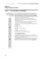
Страница 16: ...el operation insert one input and two output plugs into CH 1 MAIN CH 1 LOW and CH 1 HIGH respectively For dual channel operation insert two input and four output plugs into the sockets labelled CH 1 MAIN CH 2 MAIN CH 1 LOW CH 2 LOW CH 1 HIGH CH 2 HIGH For stereo operation we recommend the following CH 1 is designated LEFT Channel CH 2 is designated RIGHT Channel To set the crossover point turn the...

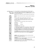
Страница 17: ...point normally lies between 800Hz and 9000Hz 9kHz For 3 way operation follow the yellow legend on the rear panel Depress the grey CROSSOVER MODE SELECTOR switch on the rear panel Now check the yellow LED marked MONO 3 WAY on the front panels left side is lit Insert one input and three output plugs into the following sockets CH 1 MAIN LOW RANGE MID RANGE HIGH RANGE See sections 9 10 for wiring deta...

Страница 18: ...tween 18Hz and 200Hz The high output is substantially a full range signal and is normally split further into 2 or 3 bands using a second active crossover As with conventional 2 way operation the FDS 310 handles up to 2 channels stereo in sub woofer mode If a mono sub woofer output is required refer to section 13 Refer to section 22 1 for information on locating the FREQ switches 11 3 2 Channel Sub...

Страница 19: ...he two outputs are used to drive different sub woofer amplifiers at different locations requiring an independent sound balance If there is only one sub woofer or the sub woofers absolutely do not require different drive levels and can therefore be driven from just one of the two outputs the unused output serves as a spare 13 0 Unusual Crossover Points for 3 way systems only This is for when a 3 wa...

Страница 20: ...4 1 When STEREO 2 WAY operation is selected CD horn equalisation can be individually setup on both CH 1 and CH 2 HIGH outputs When set to MONO 3 WAY mode the CD horn equalisation can be setup on the HIGH output Output 4 The equalisation for output 2 even if selected is automatically defeated when in 3 way mode This means the FDS 310 can be switched from 2 to 3 way operation with any combination of...

Страница 21: ...ady illumination means high drive levels Periodic flashing indicates average drive levels The LEDs will NOT LIGHT if the peak signal level stays below 15dBu 138 millivolts On each channel the red PEAK LED lights if the internal signal levels of the crossover approaches or exceeds overload They will light at levels in excess of 17dBu giving a 3dB advance warning of actual overload and clip which oc...

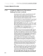
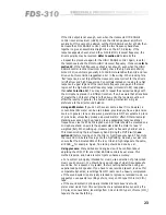
Страница 22: ...set to flat House EQ if fitted should be adjusted later once the sound systems basic response has been made as smooth as possible by adjusting the crossover The analysers microphone is positioned on axis to the speaker stack At this juncture any other speaker stacks should be muted See section 18 If you are setting up a 2 Channel stereo system tune up ONE channel at a time Set all the power amplif...

Страница 23: ...e Analyser a conventional SPL meter can be used instead provided you have a pink noise source In general tone or sine wave generators are NOT acceptable in place of pink noise unless they produce a pulsed warble effect Otherwise major standing waves can build up leading to an exaggerated response at spot frequencies Like the RTAs microphone an SPL meter should be mounted on a microphone stand on a...

Страница 24: ...ly you may want to readjust the LOW RANGE for the best balance Where ever possible note the LEVEL control settings and then challenge your colleague s to repeat the set up from scratch Compare your settings and try to arrive at a best fit if your ears disagree MUTE switch 18 0 Using the Mute switch Each frequency bands control surface includes a MUTE switch See Figure 6 1 Depressing it silences th...

Страница 25: ...s only The only problem with operating in Pin 2 HOT mode concerns the phone plugs where the ring terminal become the HOT one If the remainder of the system is wired Pin 2 HOT you may wish to reverse the sockets polarity so the tip becomes the HOT terminal Refer to section 22 5 for information on reversing polarity Aside from loudspeaker drive unit connections polarity transposition can arise in ba...

Страница 26: ... one or two outputs If the effect depends on the frequency controls setting view the panel LEDs to conform the internal FREQ switches are set correctly See sections 11 3 13 Then check level control s and output wiring Problem Excessive Hum Intermittent sound First check the connections on your input and output plugs See sections 9 10 Unshielded cables improperly wired connectors and damaged cables...

Страница 27: ...ts and outputs and because there is no input ground connection it is very unlikely that any connection problem will be experienced provided the wiring instruction in sections 9 10 have been correctly followed If the system has a very loud hum and buzzing we recommend that you check the input signal leads have their cable shields properly grounded at the source end that is at the output socket of t...

Страница 28: ... setting the crossover point disconnect the mains power remove the lid of the unit and locate the slide switches SW2 and SW3 marked divide 10 FREQ X 1 See Figure 22 1 If sub woofer operation is required on both channels set both switches to divide by 10 otherwise SW2 activates Channel 1 SW3 activates Channel 2 Replace the lid and reconnect the power The red LED marked divide by 10 below the CROSSO...

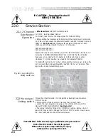
Страница 29: ...hanged according to the present operating mode and your requirements The jumper is factory fitted in the EQ OUT position Slide it out and replace it firmly so that it bridges the EQ IN position Now replace the cover plate and reconnect the mains power Fig 22 3 Locating the CD HORN EQ switches 22 3 Activating Equalisation CAUTION Important Notes SERVICE SECTION WARNING Refer all servicing to qualif...

Страница 30: ...marked incorrectly on a rogue unit Most drive unit manufacturers specify the terminal for the cone moving outward but a few hold the opposite convention If some of the drivers operating within a specific frequency range in one stack array or cluster are wired out of phase with the remainder the sound output will be partially cancelled POLARITY switching at the crossover cannot correct this situati...

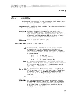
Страница 31: ...s indicate an increase and negative ones a decrease Some useful ratios are 3dB DoublePower 6dB x 2 Voltage or x 4 Power 10dB x 3 Voltage or x 10 Power 20dB x 10 Voltage or x 110 Power dBm The addition of m after dB indicates an absolute scaling for the dB ratio Instead of a ratio the dB becomes a measure of power 0dBm a power level of 1 milliwatt into a load of 600 ohms It is also loosely used to ...

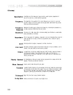
Страница 32: ...ls Line Level Generally indicates a signal whose level is between 10 and 10dBu or 14 to 6 dBV Mic level refers to levels around 40dBu Octave A logarithmic unit for expressing frequency ratios Positive values indicate an increase and negative ones a decrease One octave up the scale is equivalent to a doubling in frequency One octave down is equivalent to a halving of frequency Polarity Reversal An ...

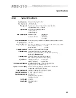
Страница 33: ...order Linkwitz Riley Tuneable 2 way LOW HIGH range 180Hz to 2000Hz 2kHz Frequency range is divisible by 10 with internal switching see sections SUB WOOFER Tuneable 3 way LOW MID range 180Hz to 2000Hz 2kHz MID HIGH range 800Hz to 9000Hz 9kHz Input Filtration 18dB OCT ultrasonic 3dB at 30Hz 6dB OCTsubsonic 3dB at 15Hz THD Harmonic Distortion Including residual noise 0 03 THD up to MOL Typically 0 01...

Страница 34: ...repaid You should include a statement listing the faults found The unit s serial number must be quoted in all correspondence relating to a claim We recommend that you record your purchase information here for future reference Dealer Name Dealer Address Post Zip Code Dealer Phone No Dealer Contact Name Invoice Receipt No Date of Purchase Unit Serial Number In keeping with our policy of continued im...

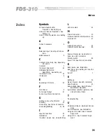
Страница 35: ...Input Connections 14 Installation 12 Invisible slopes See Linkwitz Riley L LED indicators 24 M Mains Connection 13 Monaural Sub Woofer Operation 20 Mute switch 27 O Output Connections 15 Output Polarity Reversal 28 P Passive Crossovers See Section 2 Peak See LED indicators Polarity switch 28 Power ON See Mains Connection R Rack space See Installation Rear Panel See Getting to know the FDS 310 Roll...

Страница 36: ...3 6 W Warranty Info 34 Wiring Convention See Input Connections Output Connec tions X XLR Plugs See Input Connections Z Zero Phase difference See Linkwitz Riley filters Index ...

Страница 37: ...37 User Notes ...

Страница 38: ...3 8 User Notes ...

Страница 39: ...39 User Notes ...

Страница 40: ...4 0 User Notes ...

Отзывы: