3 0
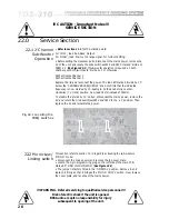
• Disconnect the power and remove the top cover plate.
• Locate the green wire bolted to the chassis on the right side of the toroidal
transformer. Check the wire connects to the PCB terminal marked 'CHASSIS'
(
See figure 22.4
).
• Remove the tag from the chassis bolt, or alternatively unsolder its other end
from the circuit board.
Either way, do not leave the wire hanging loose; fold it
over and sleeve for continued safety.
Fig 22.4 Locating the
CHASSIS point
22.4 Eliminating
Hum
• Disconnect the power and remove the top cover plate.
• Locate the 1 ohm resistor links behind the phone plug sockets. These are
factory set to position 'A'.
• To reverse the polarity, remove the underside cover-plate, de-solder the
links and replace in position 'B'. The importance of ensuring that all the
drivers in a stack, array or cluster are 'in phase' (meaning they all 'push and
pull' in synchronisation) is well known, although mistakes can occur.
Sometimes, the driver polarity is marked incorrectly on a rogue unit. Most
drive unit manufacturers specify the '+' terminal for the cone moving outward,
but a few hold the opposite convention. If some of the drivers operating
within
a specific frequency range in one stack, array or cluster are wired 'out of
phase' with the remainder, the sound output will be partially cancelled.
POLARITY switching at the crossover cannot correct this situation.
If the drivers operating in one frequency range are wired 'out of phase' with
the other frequency band(s), the response at the crossover will exhibit an
audible irregularity, either as a peak or a dip. Use the POLARITY switches to
test this. Depress and release each in turn if you suspect that one frequency
band is wired 'out of phase'. If switching doesn't improve the sound, and the
dip or peak is appreciable, the cause is undoubtedly acoustic, to do with the
drive-unit spacing and path lengths.
22.5 Polarity
Switching
!!! CAUTION - Important Notes !!!
SERVICE SECTION
!!! WARNING - Refer all servicing to qualified service personnel !!!
Risk of electric shock if the unit is opened.
BSS Audio accepts no responsibility for injury
subsequent to opening of the unit.
Содержание FDS 310
Страница 1: ...1 FDS 310 User Manual ...
Страница 10: ...1 0 Getting to know the FDS 310 Fig 6 1 Front Panel Fig 6 2 Rear Panel ...
Страница 11: ...11 All numbers in bubbles refer to Section numbers ...
Страница 37: ...37 User Notes ...
Страница 38: ...3 8 User Notes ...
Страница 39: ...39 User Notes ...
Страница 40: ...4 0 User Notes ...

