6
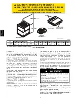
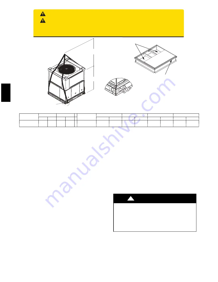
ACCESS PANELS MUST BE IN PLACE WHEN RIGGING.
PANNEAUX D'ACCES DOIT ÊTRE EN PLACE POUR MANIPULATION.
50CY502286 2.0
CAUTION - NOTICE TO RIGGERS
PRUDENCE - AVIS AUX MANIPULATEUR
Use top skid as spreader bar. / Utiliser la palette du haut comme barre de répartition
SEAL STRIP MUST BE IN
PLACE BEFORE PLACING
UNIT ON ROOF CURB
DUCTS
DETAIL A
VOIR DÉTAIL A
MINIMUM HEIGHT: 36" (914.4 mm)
HAUTEUR MINIMUM
UNIT HEIGHT
HAUTEUR D'UNITÉ
SEE DETAIL A
VOIR DÉTAIL A
BANDE SCELLANT DOIT ÊTRE
EN PLACE AVANT DE PLACER
L'UNITÉ SUR LA BASE DE TOIT
A09051
Unit
24
30
Unit
36
42
48
60
lb
kg
lb
kg
lb
kg
lb
kg
lb
kg
lb
kg
Rigging
Weight
365
166
395
179
Rigging
Weight
440
200
475
215
500
227
515
234
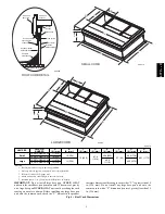
NOTE: See dimensional drawing for corner weight distribution.
Fig. 5 -- Suggested Rigging
SLAB MOUNT
Place the unit on a solid, level pad that is at least 2 in. (51 mm)
above grade. The pad should extend approximately 2 in. (51 mm)
beyond the casing on all 4 sides of the unit. Do not secure the unit
to the pad
except
when required by local codes.
Step 3 — Field Fabricate Ductwork
Secure all ducts to roof curb and building structure on vertical
discharge units. Do not connect ductwork to unit. For horizontal
applications, unit is provided with flanges on the horizontal
openings. All ductwork should be secured to the flanges. Insulate
and weatherproof all external ductwork, joints, and roof openings
with counter flashing and mastic in accordance with applicable
codes.
Ducts passing through an unconditioned space must be insulated
and covered with a vapor barrier.
If a plenum return is used on a vertical unit, the return should be
ducted through the roof deck to comply with applicable fire codes.
Read unit rating plate for any required clearances around ductwork.
Cabinet return--air static shall not exceed --.25 IN. W.C.
Step 4 — Provide Clearances
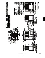
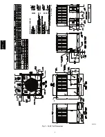
The required minimum operating and service clearances are shown
in Fig. 2 and 3.
IMPORTANT
: Do not restrict outdoor airflow. An air restriction
at either the outdoor--air inlet or the fan discharge may be
detrimental to compressor life.
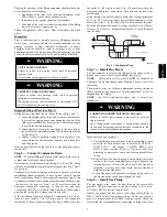
The condenser fan pulls air through the condenser coil and
discharges it through the top grille. Be sure that the fan discharge
does not recirculate to the condenser coil. Do not locate the unit in
either a corner or under an overhead obstruction. The minimum
clearance under a partial overhang (such as a normal house
overhang) is 48--in. (1219 mm) above the unit top. The maximum
horizontal extension of a partial overhang must not exceed 48--in.
(1219 mm).
Do not place the unit where water, ice, or snow from an overhang
or roof will damage or flood the unit. Do not install the unit on
carpeting or other combustible materials. The unit may be installed
on wood flooring or on Class A, B, or C roof covering materials.
Step 5 — Rig and Place Unit
PERSONAL INJURY OR PROPERTY DAMAGE
HAZARD
Failure to follow this warning could result in personal
injury, death or property damage.
When installing the unit on a rooftop, be sure the roof will
support the additional weight.
!
WARNING
Rigging and handling of this equipment can be hazardous for
many reasons due to the installation location (roofs, elevated
structures, etc.).
Only trained, qualified crane operators and ground support staff
should handle and install this equipment.
When working with this equipment, observe precautions in the
literature, on tags, stickers, and labels attached to the equipment,
and any other safety precautions that might apply.
677C
--
--
C
Содержание Legacy 677C**C Series
Страница 3: ...3 A150538 Fig 2 24 30 Unit Dimensions 677C C...
Страница 4: ...4 A150539 Fig 3 36 60 Unit Dimensions 677C C...
Страница 44: ...44 A150506 Fig 15 208 230 1 60 Connection Wiring Diagram 677C C...
Страница 45: ...45 A150516 Fig 15 Cont 208 230 1 60 Ladder Wiring Diagram 677C C...
Страница 46: ...46 A150507 Fig 16 208 230 3 60 Connection Wiring Diagram 677C C...
Страница 47: ...47 A150517 Fig 16 Cont 208 230 3 60 Ladder Wiring Diagram 677C C...


