


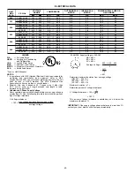

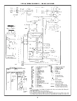


TYPICAL WIRING SCHEMATIC — 208/230-1-60 SHOWN
LEGEND
AHA
—
Adjustable
Heat
Anticipator
BR
—
Blower
Relay
C—
Contactor
CAP
—
Capacitor
COMP
—
Compressor
Motor
CR
—
Combustion
Relay
EQUIP
—
Equipment
FS
—
Flame
Sensor
FU
—
Fuse
GND
—
Ground
GVR
—
Gas
V
alve
Relay
HS
—
Hall
Ef
fect
Sensor
HV
—
High
V
oltage
T
ransformer
TRAN
—
T
ransformer
I—
Ignitor
IDM
—
Induced-Draft
Motor
IFM
—
Indoor-Fan
Motor
IGC
—
Integrated
Gas
Unit
Controller
LS
—
Limit
Switch
MGV
—
Main
Gas
V
alve
NEC
—
National
Electrical
Code
OFM
—
Outdoor-Fan
Motor
QT
—
Quadruple
T
erminal
RS
—
Rollout
Switch
TRAN
—
T
ransformer
Field
Splice
T
erminal
(Marked)
T
erminal
(Unmarked)
Splice
Splice
(Marked)
Factory
Wiring
Field
Control
Wiring
Field
Power
Wiring
Accessory
or
Optional
Wiring
T
o
Indicate
Common
Potential
Only
,
Not
to
Represent
Wiring
NOTES:
1.
If
any
of
the
original
wires
furnished
are
replaced,
it
must
be
replaced
with
type
90
degree
C
wire
or
its
equivalent.
2.
See
T
rade
Prices
for
thermostat
and
subbases.
3.
Use
75
degree
C
copper
conductors
for
field
installation.
4.
For
high
speed
IFM,
disconnect
RED
wire
from
IGC
terminal
BM
and
connect
BLK
wire
from
IFM.
For
medium
speed,
disconnect
RED
wire
from
IGC
terminal
BM
and
connect
BLU
wire
from
IFM.
5.
Models
583A
sizes
024-036
have
LS1
and
LS2
wired
in
series.
Models
583A
sizes
042-060
have
LS1
only
.
21


