


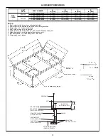


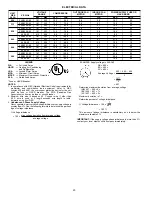

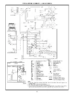

BASE UNIT DIMENSIONS — UNIT SIZES 024-036
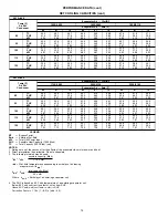
REQ’D CLEARANCES FOR OPERATION AND SERVICING. in. (mm)
Evaporator coil access side . . . . . . . . . . . . . . . . . . . . 36 (914)
Power entry side (except for NEC requirements)
. . . . . . . . . . 36 (914)
Unit top . . . . . . . . . . . . . . . . . . . . . . . . . . . . 48 (1219)
Side opposite ducts . . . . . . . . . . . . . . . . . . . . . . . 36 (914)
Duct panel . . . . . . . . . . . . . . . . . . . . . . . . . . 12 (304.8)*
*Minimum distances: If unit is placed less than 12 in. (304.8 mm) from wall system,
then the system performance may be compromised.
REQ’D CLEARANCES TO COMBUSTIBLE MAT’L. in. (mm)
Top of unit . . . . . . . . . . . . . . . . . . . . . . . . . 14 (355.6)
Duct side of unit . . . . . . . . . . . . . . . . . . . . . . . 2 (50.8)
Side opposite ducts . . . . . . . . . . . . . . . . . . . . . 14 (355.6)
Bottom of unit . . . . . . . . . . . . . . . . . . . . . . . 0.50 (12.7)
Flue panel . . . . . . . . . . . . . . . . . . . . . . . . . 36 (914.4)
NEC REQ’D CLEARANCES. in. (mm)
Between units, power entry side
. . . . . . . . . . . . . . 42 (1066.8)
Unit and ungrounded surfaces, power entry side . . . . . . . . . 36 (914)
Unit and block or concrete walls and other grounded
surfaces, control box side
. . . . . . . . . . . . . . . . . 42 (1066.8)
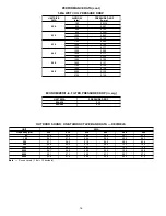
UNIT
583A
ELECTRICAL
CHARACTERISTICS
UNIT WEIGHT
UNIT HEIGHT
in. [mm]
‘‘A’’
CENTER OF GRAVITY
in. [mm]
lb
kg
X
Y
Z
024040/060
208/230-1-60
290.0
639.3
35.02 [889.5]
22.0 [558.8]
14.5 [368.3]
16.0 [406.4]
030040/060
208/230-1-60, 208/230-3-60
313.0
690.0
39.02 [991.1]
22.0 [558.8]
15.3 [387.4]
17.6 [447.0]
036060/090
208/230-1-60, 208/230-3-60, 460-3-60
321.0
707.7
35.02 [889.5]
22.0 [558.8]
15.3 [387.4]
16.5 [419.1]
LEGEND
CG
— Center of Gravity
COND
— Condenser
EVAP
— Evaporator
NEC
— National Electrical Code
REQ’D — Required
NOTE: Dimensions are in mm [in.].
8


