58
3. Make the following inspections:
a. Inspect for shipping and handling damages such
as broken lines, loose parts, or disconnected
wires, etc.
b. Inspect for oil at all refrigerant tubing connec-
tions and on unit base. Detecting oil generally
indicates a refrigerant leak. Leak
−
test all refrig-
erant tubing connections using electronic leak
detector, halide torch, or liquid
−
soap solution.
c. Inspect all field
−
wiring and factory
−
wiring con-
nections. Be sure that connections are completed
and tight. Be sure that wires are not in contact
with refrigerant tubing or sharp edges.
d. Inspect coil fins. If damaged during shipping and
handling, carefully straighten fins with a fin
comb.
4. Verify the following conditions:
a. Make sure that condenser
−
fan blade are correctly
positioned in fan orifice. See Condenser
−
Fan
Adjustment section for more details.
b. Make sure that air filter(s) is in place.
c. Make sure that condensate drain trap is filled
with water to ensure proper drainage.
d. Make sure that all tools and miscellaneous loose
parts have been removed.
START
−
UP, GENERAL
Unit Preparation
Make sure that unit has been installed in accordance with
installation instructions and applicable codes.
IMPORTANT
: Follow the base unit’s start-up sequence
as described in the unit’s installation instructions:
In addition to the base unit start-up, there are a few steps
needed to properly start-up the controls. RTU-OPEN’s
Service Test function should be used to assist in the base
unit start-up and also allows verification of output
operation. Controller configuration is also part of start-up.
This is especially important when field accessories have
been added to the unit. The factory pre-configures options
installed at the factory. There may also be additional
installation steps or inspection required during the start-up
process.
Additional Installation/Inspection
Inspect the field installed accessories for proper
installation, making note of which ones do or do not
require configuration changes. Inspect the RTU-OPEN’s
Alarms for initial insight to any potential issues. Refer to
the following manual:
“Controls, Start
−
up, Operation and
Troubleshooting Instructions.”
Inspect the SAT sensor for
relocation as intended during installation. Inspect special
wiring as directed below.
Gas Piping
Check gas piping for leaks.
!
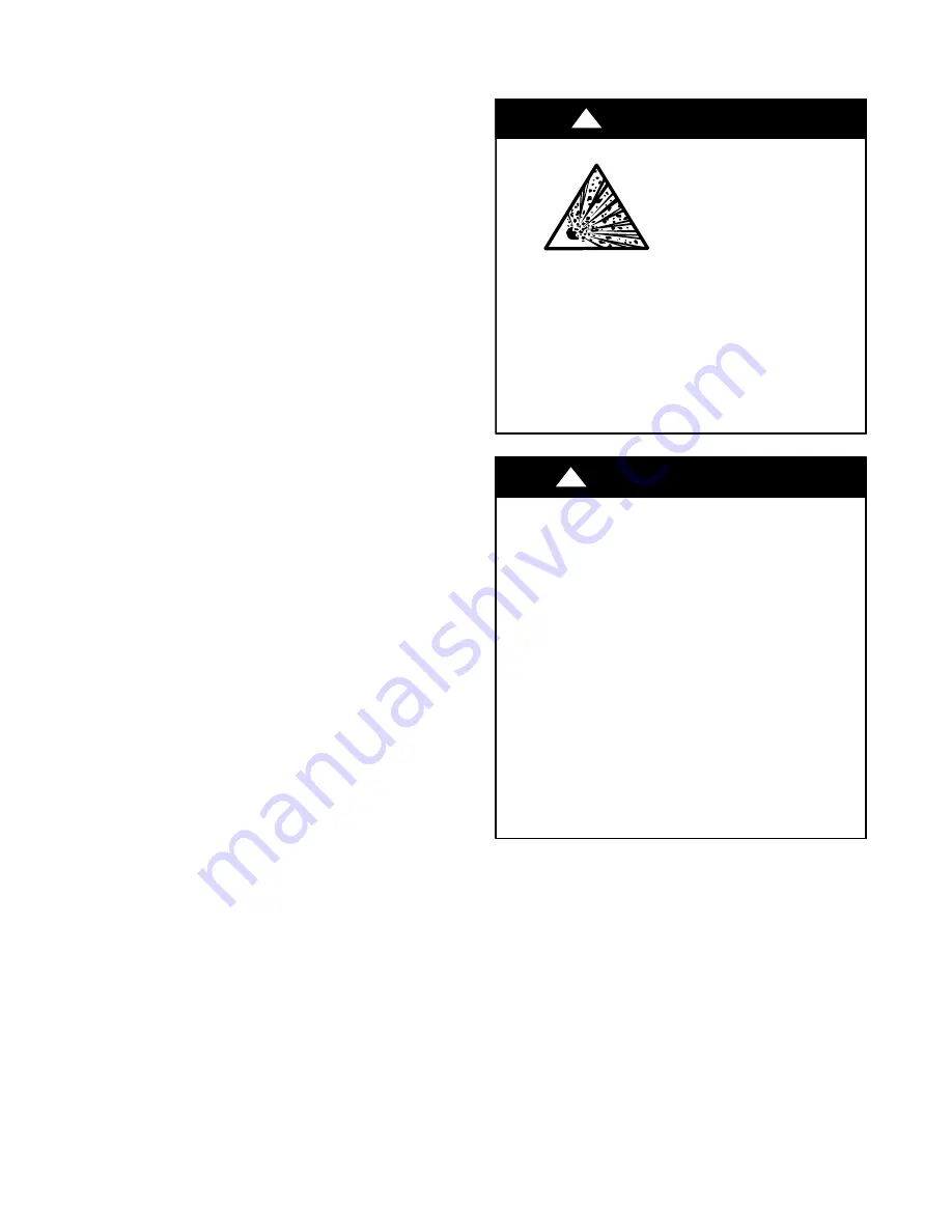
WARNING
FIRE, EXPLOSION HAZARD
Failure to follow this
warning could result in
death, serious personal
injury and/or property
damage.
Disconnect gas piping from unit when pressure testing
at pressure greater than 0.5 psig. Pressures greater than
0.5 psig will cause gas valve damage resulting in haz-
ardous condition. If gas valve is subjected to pressure
greater than 0.5 psig, it
must
be replaced before use.
When pressure testing field-supplied gas piping at
pressures of 0.5 psig or less, a unit connected to such
piping must be isolated by closing the manual gas
valve(s).
FIRE, EXPLOSION HAZARD
Failure to follow this warning could result in
personal injury, death and/or property damage.
Refer to the User’s Information Manual provided
with this unit for more details.
Do not store or use gasoline or other flammable
vapors and liquids in the vicinity of this or any other
appliance.
What to do if you smell gas:
DO NOT
try to light any appliance.
DO NOT
touch any electrical switch, or use any
phone in your building.
IMMEDIATELY
call your gas supplier from a
neighbor’s phone. Follow the gas supplier’s
instructions.
If you cannot reach your gas supplier, call the fire
department.
!
WARNING
Return
−
Air Filters
Ensure correct filters are installed in unit (see Appendix II
−
Physical Data). Do not operate unit without return
−
air
filters.
Outdoor
−
Air Inlet Screens
Outdoor
−
air inlet screen must be in place before operating
unit.
Compressor Mounting
Compressors are internally spring mounted. Do not loosen
or remove compressor hold down bolts.
Internal Wiring
Check all electrical connections in unit control boxes.
Tighten as required.
Содержание 580J D17
Страница 80: ...80 APPENDIX IV WIRING DIAGRAMS cont C160041 Fig 72 580J D17 D28 Control Diagram 208 230 3 60 460 575 3 60 ...
Страница 81: ...81 APPENDIX IV WIRING DIAGRAMS cont C160042 Fig 73 580J D17 D28 Power Diagram 208 230 3 60 ...
Страница 82: ...82 APPENDIX IV WIRING DIAGRAMS cont C160043 Fig 74 580J D17 D28 Power Diagram 460 3 60 ...
Страница 83: ...83 APPENDIX IV WIRING DIAGRAMS cont C160044 Fig 75 580J D17 D28 Power Diagram 575 3 60 ...
Страница 84: ...84 APPENDIX IV WIRING DIAGRAMS cont C160050 Fig 76 580J D17 D28 Control Diagram with Perfect Humidity ...
Страница 86: ...86 APPENDIX IV WIRING DIAGRAMS cont C160047 Fig 78 580J D17 D28 Power Diagram 460 3 60 with Perfect Humidity ...
Страница 87: ...87 APPENDIX IV WIRING DIAGRAMS cont C160048 Fig 79 580J D17 D28 Power Diagram 575 3 60 with Perfect Humidity ...
Страница 88: ...88 APPENDIX IV WIRING DIAGRAMS cont C160049 Fig 80 RTU OPEN Wiring Diagram ...
Страница 89: ...89 APPENDIX IV WIRING DIAGRAMS cont C160045 Fig 81 RTU OPEN Wiring Diagram with Perfect Humidity ...


