background image

PRE-START-UP

WARNING:

Failure to observe the following warn-

ings could result in serious personal injury:

1. Follow recognized safety practices and wear pro-

tective goggles when checking or servicing refrig-
erant system.

2. Do not operate compressor or provide any electric

power to unit unless compressor terminal cover is
in place and secured.

3. Do not remove compressor terminal cover until all

electrical sources have been disconnected.

4. Relieve all pressure from system before touching

or disturbing anything inside terminal box if
refrigerant leak is suspected around compressor
terminals. Use accepted methods to recover
refrigerant.

5. Never attempt to repair soldered connection while

refrigerant system is under pressure.

6. Do not use torch to remove any component. Sys-

tem contains oil and refrigerant under pressure.
To remove a component, wear protective goggles
and proceed as follows:
a. Shut off all power to unit.
b. Reclaim refrigerant to relieve all pressure from

system using both high- and low-pressure ports.

c. Cut component-connecting tubing with tubing

cutter and remove component from unit.

d. Carefully unsweat remaining tubing stubs when

necessary. Oil can ignite when exposed to torch
flame.

Proceed as follows to inspect and prepare the unit for initial
start-up:

1. Remove all access panels.

2. Read and follow instructions on all WARNING, CAU-

TION, and INFORMATION labels attached to, or shipped
with, unit.

3. Make the following inspections:

a. Inspect for shipping and handling damages such as

broken lines, loose parts, disconnected wires, etc.

b. Inspect for oil at all refrigerant tubing connections

and on unit base. Detecting oil generally indicates a
refrigerant leak. Leak-test all refrigerant tubing con-
nections using electronic leak detector, halide torch,
or liquid-soap solution. If refrigerant leak is de-
tected, see Refrigerant Leaks section on page 31.

c. Inspect all field- and factory-wiring connections. Be

sure that connections are completed and tight.

d. Inspect coil fins. If damaged during shipping and han-

dling, carefully straighten fins with a fin comb.

4. Verify the following conditions:

a. Make sure that condenser-fan blade is positioned cor-

rectly in fan orifice. Blades should clear fan motor
and fan orifice ring.

b. Make sure that air filters are in place. (See Table 1.)

Do not operate unit without return-air filters.

c. Make sure that condensate drain pan and trap are

filled with water to ensure proper drainage.

d. Make sure that all tools and miscellaneous loose parts

have been removed.

e. Make sure outdoor-air inlet screens are in place.

5. Compressors are internally spring mounted. Do not loosen

or remove compressor holddown bolts.

6. Each unit system has 4 Schrader-type service ports: one

on the suction line, one on the liquid line and two on
the compressor discharge line. Be sure that caps on the
ports are tight.

Unit is now ready for initial start-up.

START-UP

I. COMPRESSOR ROTATION

On 3-phase units, it is important to be certain the scroll com-
pressor is rotating in the proper direction. To determine whether
or not compressor is rotating in the proper direction:

1. Connect service gages to suction and discharge pres-

sure fittings.

2. Energize the compressor.

3. The suction pressure should drop and the discharge pres-

sure should rise, as is normal on any start-up.

If the suction pressure does not drop and the discharge pres-
sure does not rise to normal levels:

1. Note that the evaporator fan (060 and 072 only) is prob-

ably also rotating in the wrong direction.

2. Turn off power to the unit.

3. Reverse any two of the unit power leads.

4. Turn on power to the compressor.

The suction and discharge pressure levels should now move
to their normal start-up levels.

NOTE:

When the compressor is rotating in the wrong direc-

tion, the unit makes an elevated level of noise and does not
provide cooling.

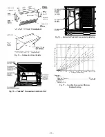
Fig. 25 — Filter Installed On Outdoor Air Hood

—17—

Содержание 551B Series

Страница 1: ... WARNING Before performing service or mainte nance operations on unit turn off main power switch to unit Electrical shock could cause personal injury 1 The power supply volts hertz and phase must corre spond to that specified on unit rating plate 2 The electrical supply provided by the utility must be suf ficient to handle load imposed by this unit 3 Refer to Locate the Unit section on page 3 and ...

Страница 2: ...6 With the exception of the clearance for the condenser coil and combustible surfaces as stated in notes 5a b and c a removable fence or barricade re quires no clearance 7 Units may be installed on combustible floors made from wood or class A B or C roof covering material 8 The vertical center of gravity is 18 61 29 470 up from the bottom of the base rail UNIT STD UNIT WEIGHT VARISLIDE ECONOMIZER ...

Страница 3: ... gravel apron in front of condenser coil air inlet to prevent grass and foliage from obstructing airflow NOTE Horizontal units may be installed on a roof curb if required II UNIT DUCT CONNECTIONS On vertical units secure all ducts to roof curb and building structure Do not connect ductwork to unit On horizontal units field supplied duct flanges should be attached to horizontal openings and all duc...

Страница 4: ...de 7 Direction of airflow UNIT SIZE SERVICE PLATE SIZES B C D Alt Drain Hole F Power G Control Connector Package Accessory 551B036 072 2111 169 551 169 406 13 49 44 5 3 49 or 11 49 NPT 3 49 NPT 314213 203 THRU THE SIDE 3 49 NPT 1 29 NPT CRBTMPWR001A00 THRU THE BOTTOM 11 49 NPT 1 29 NPT CRBTMPWR002A00 THRU THE BOTTOM ROOF CURB ACCESSORY A UNIT SIZE CRRFCURB001A00 149 356 551B036 072 CRRFCURB002A00 ...

Страница 5: ...type air conditioning and ventilating systems NFPA No 90A or residence type NFPA No 90B and or local codes and ordinances Adhere to the following criteria when selecting sizing and installing the duct system 1 Remove appropriate panels from unit to obtain either horizontal or vertical discharge If units are installed in horizontal discharge applications remove vertical dis charge duct covers save ...

Страница 6: ...ype Ball Ball Ball Ball Maximum Fan Rpm 2100 2100 2100 2100 Motor Pulley Pitch Diameter A B in 1 9 2 9 1 9 2 9 2 4 3 4 2 4 3 4 Nominal Motor Shaft Diameter in 1 2 1 2 1 2 5 8 Fan Pulley Pitch Diameter in 4 5 4 0 4 0 3 7 Belt Qty Type Length in 1 A 33 1 A 36 1 A 40 1 A 38 Pulley Center Line Distance in 10 0 12 4 10 0 12 4 14 7 15 5 14 7 15 5 Speed Change per Full Turn of Movable Pulley Flange rpm 6...

Страница 7: ...of and vibration isolate all openings in building structure in accordance with local codes and good building practices C Electrical Connections WARNING The unit cabinet must have an uninter rupted unbroken electrical ground to minimize the pos sibility of personal injury if an electrical fault should occur This ground may consist of electrical wire con nected to the unit ground lug in the control ...

Страница 8: ...nnector Install conduit connectors in side panel power supply knockout openings indicated in Fig 2 Route power lines through connector to unit control box NOTE If accessory thru the bottom connections are used re fer to the thru the bottom accessory installation instructions for information on wiring the unit Refer to Fig 2 for loca tions to drill holes through the basepan Special Procedures for 2...

Страница 9: ...ce Connection Factory Supplied IFC Indoor Evaporator Fan Contactor NEC National Electrical Code Fig 10 Power Wiring Connections 460 3 60 SIZES 036 048 208 230 3 60 460 3 60 SIZE 060 AND 072 575 3 60 SIZE 060 AND 072 208 230 3 60 SIZES 036 048 208 230 1 60 SIZES 036 060 575 3 60 SIZES 036 048 9 ...

Страница 10: ...0 5 22 5 22 5 23 1 25 7 28 8 32 3 47 8 54 2 60 8 69 3 30 30 30 30 30 35 50 60 70 80 22 22 22 24 27 30 44 50 56 64 112 112 460 3 60 414 508 7 4 49 5 0 4 2 2 6 0 11 5 13 8 23 0 7 2 13 8 16 6 27 7 9 7 11 8 20 0 23 5 37 3 15 15 25 25 40 12 12 18 22 34 57 575 3 60 518 632 5 8 40 0 0 4 2 2 9 3 15 9 46 060 5 Tons 208 230 1 60 187 254 28 8 169 0 1 5 8 8 4 9 6 5 6 5 8 7 9 8 13 0 13 1 17 4 15 8 21 0 23 5 27...

Страница 11: ...8 50 5 28 5 28 5 28 5 30 7 33 8 37 3 52 8 59 2 65 8 74 3 35 35 35 35 35 40 60 60 70 80 28 28 28 29 32 35 50 55 62 69 117 117 460 3 60 414 508 7 4 49 5 0 4 2 2 6 0 11 5 13 8 23 0 7 2 13 8 16 6 27 7 14 6 15 1 22 7 26 2 40 0 20 20 25 30 45 14 14 21 24 37 59 575 3 60 518 632 5 8 40 0 0 4 2 2 11 5 15 11 47 060 5 Tons 208 230 1 60 187 254 28 8 169 0 1 5 8 8 4 9 6 5 6 5 8 7 9 8 13 0 13 1 17 4 15 8 21 0 2...

Страница 12: ...ance 100 x 457 1 53 This amount of phase imbalance is satisfactory as it is below the maxi mum allowable 2 IMPORTANT If the supply voltage phase imbalance is more than 2 contact your local electric utility company immediately 3 575 v units are CUL approved only electric heaters are not avail able for 575 v units Table 3 Thermostats TYPE Manual Changeover Standard 1 Heat 1 Cool 2 Heat 2 Cool Auto C...

Страница 13: ...ccess panel Ensure the filter access panel slides along the tracks and is securely engaged 10 Fasten hood top and side plate assembly Fig 14 to outdoor air opening panel with screws provided 11 Place knob supplied with economizer on OAT See Fig 18 Set for 3 F below indoor room thermostat set ting If accessory enthalpy control EC is used in place of OAT see instructions shipped with EC for installa...

Страница 14: ...it BAROMETRIC RELIEF DAMPER ECONOMIZER MOTOR ECONOMIZER CONTROL BOARD WIRING HARNESS Fig 16 Horizontal Varislide Economizer Installation Example Given Negative Pressure 0 2 in wg Outdoor Air 900 cfm Determine Setting 5 in Fig 17 Varislide Economizer Minimum Position Setting 14 ...

Страница 15: ... cfm3 cfm1 T1 T2 If cfm1 does not match the desired minimum air flow from Step 1 re adjust the minimum position set ting screw MINIMUM POSITIO N OPEN 3 1 T P P1 T1 4 2 5 S S O D C TR B REV B 1 9 8 8 1 8 A H U M I D I T Y 90 70 60 30 10 D C B A 60 65 70 75 55 50 85 80 DAMPER DAMPER CLOSED OPEN OUTDOOR TEMP F REV 97 3672 CW SETPOINTS CCW CONTACTS SHOWN IN HIGH ENTHALPY RUSH AT 24VAC 3 mA MIN AT 11 V...

Страница 16: ...ter access panel slides along the tracks and is securely en gaged See Fig 23 9 Fasten hood top and side plate assembly Fig 24 to outdoor air opening panel with screws provided 10 Slide outdoor air inlet screen into screen track on hood side plate While holding screen in place fasten screen retainer to hood using screws provided See Fig 25 Fig 21 PARABLADE Economizer Installed in Unit CONTROL CURVE...

Страница 17: ... Refrigerant Leaks section on page 31 c Inspect all field and factory wiring connections Be sure that connections are completed and tight d Inspect coil fins If damaged during shipping and han dling carefully straighten fins with a fin comb 4 Verify the following conditions a Make sure that condenser fan blade is positioned cor rectly in fan orifice Blades should clear fan motor and fan orifice ri...

Страница 18: ...ed manual limit switch LSM The LSM is located on the fan housing and will only open in the event of a fan failure The LSM re set button is located between terminals on the switch F Airflow and Temperature Rise The heating operation airflow must produce a temperature rise that falls within the approved cfm range 300 to 500 cfm per 12 000 Btuh cooling Refer to Indoor Airflow and Airflow Adjustments ...

Страница 19: ...in in an in termediate open position If the supply air temperature falls below 52 F a switch on the supply air thermostat is closed between the T1 terminal and the 24 vac terminal This causes the damper to modu late closed until the supply air temperature rises above 55 F or the damper reaches the minimum position When the supply air temperature is between 55 F and 57 F the supply air thermostat h...

Страница 20: ... from fixed flange to decrease speed Increasing fan speed increases load on motor Do not exceed maxi mum speed specified in Table 1 5 Set movable flange at nearest keyway of pulley hub and tighten setscrew See Table 1 for speed change for each full turn of pulley flange To align fan and motor pulleys see Fig 27 1 Loosen fan pulley setscrews 2 Slide fan pulley along fan shaft 3 Make angular alignme...

Страница 21: ... 62 1067 0 67 1500 841 0 42 911 0 53 985 0 61 1029 0 66 1073 0 72 1109 0 77 AIRFLOW Cfm BELT DRIVE MOTOR External Static Pressure in wg 0 7 0 8 0 9 1 0 1 1 1 2 Rpm Bhp Rpm Bhp Rpm Bhp Rpm Bhp Rpm Bhp Rpm Bhp 900 957 0 39 988 0 43 1039 0 45 1061 0 47 1083 0 53 1105 0 57 1000 992 0 44 1039 0 49 1061 0 51 1086 0 55 1111 0 59 1136 0 63 1100 1013 0 49 1068 0 55 1090 0 58 1109 0 61 1127 0 64 1145 0 67 1...

Страница 22: ...52 0 83 1087 0 90 1121 0 96 1183 1 09 1255 1 22 1305 1 38 1500 1076 0 91 1111 0 99 1145 1 06 1208 1 20 1274 1 33 1337 1 47 1600 1100 1 00 1134 1 08 1168 1 15 1232 1 31 1291 1 46 1350 1 60 1700 1124 1 09 1158 1 17 1192 1 25 1255 1 42 1314 1 58 1370 1 77 1800 1147 1 18 1182 1 27 1217 1 36 1279 1 54 1381 1 71 1393 1 89 1900 1169 1 27 1205 1 37 1240 1 47 1303 1 66 1408 1 85 1417 2 03 2000 1194 1 38 12...

Страница 23: ... 1403 1 69 1800 1235 1 29 1303 1 48 1371 1 69 1433 1 90 1900 1266 1 40 1330 1 59 1396 1 81 1460 2 03 2000 1297 1 53 1362 1 73 1422 1 94 1485 2 16 2100 1327 1 66 1393 1 87 1452 2 08 1510 2 31 2200 1359 1 81 1423 2 02 1483 2 24 1538 2 46 2300 1392 1 97 1454 2 18 1515 2 41 1569 2 64 2400 1426 2 15 1485 2 36 1544 2 59 1601 2 84 2500 1461 2 34 1518 2 55 1575 2 78 LEGEND Bhp Brake Horsepower Input to Fa...

Страница 24: ... 1433 1 90 1900 1266 1 40 1330 1 59 1396 1 81 1460 2 03 2000 1297 1 53 1362 1 73 1422 1 94 1485 2 16 2100 1327 1 66 1393 1 87 1452 2 08 1510 2 31 2200 1359 1 81 1423 2 02 1483 2 24 1538 2 46 2300 1392 1 97 1454 2 18 1515 2 41 1569 2 64 2400 1426 2 15 1485 2 36 1544 2 59 1601 2 84 2500 1461 2 34 1518 2 55 1575 2 78 2600 1497 2 54 1552 2 76 2700 1532 2 75 2800 2900 3000 LEGEND Bhp Brake Horsepower I...

Страница 25: ...60 0 39 1005 0 43 1052 0 49 1100 0 52 1163 0 59 1225 0 65 1200 960 0 45 1038 0 50 1076 0 53 1136 0 59 1201 0 65 1266 0 72 1300 1012 0 51 1061 0 56 1090 0 61 1172 0 65 1239 0 72 1306 0 79 1400 1027 0 56 1071 0 60 1108 0 67 1208 0 70 1278 0 79 1347 0 87 1500 1056 0 63 1097 0 68 1117 0 70 1245 0 74 1315 0 87 1385 0 96 LEGEND Bhp Brake Horsepower Input to Fan NOTES 1 Boldface indicates a field supplie...

Страница 26: ...1400 1042 0 81 1080 0 88 1118 0 95 1175 1 06 1206 1 09 1244 1 12 1500 1060 0 88 1098 0 96 1136 1 04 1205 1 19 1258 1 30 1289 1 34 1600 1080 0 95 1117 1 04 1153 1 12 1224 1 29 1287 1 45 1337 1 56 1700 1101 1 03 1137 1 12 1172 1 20 1241 1 38 1307 1 56 1366 1 73 1800 1122 1 11 1157 1 20 1192 1 29 1258 1 48 1323 1 67 1385 1 86 1900 1143 1 21 1179 1 30 1214 1 39 1279 1 58 1341 1 78 1402 1 98 2000 1165 ...

Страница 27: ...0 1800 1178 1 14 1249 1 32 1316 1 52 1382 1 72 1900 1201 1 23 1274 1 43 1338 1 62 1402 1 83 2000 1226 1 33 1297 1 53 1363 1 73 1424 1 94 2100 1252 1 45 1320 1 64 1388 1 85 1448 2 07 2200 1280 1 58 1345 1 77 1410 1 97 1473 2 20 2300 1309 1 71 1372 1 91 1434 2 11 1496 2 34 2400 1336 1 85 1400 2 06 1459 2 26 1519 2 48 2500 1363 2 00 1428 2 22 1486 2 43 1543 2 65 LEGEND Bhp Brake Horsepower Input to F...

Страница 28: ...62 1402 1 83 2000 1226 1 33 1297 1 53 1363 1 73 1424 1 94 2100 1252 1 45 1320 1 64 1388 1 85 1448 2 07 2200 1280 1 58 1345 1 77 1410 1 97 1473 2 20 2300 1309 1 71 1372 1 91 1434 2 11 1496 2 34 2400 1336 1 85 1400 2 06 1459 2 26 1519 2 48 2500 1363 2 00 1428 2 22 1486 2 43 1543 2 65 2600 1390 2 15 1456 2 38 1514 2 61 1569 2 83 2700 1418 2 31 1483 2 56 1543 2 80 2800 1446 2 48 1510 2 73 2900 1476 2 ...

Страница 29: ...s personal injury 1 Turn off electrical power to the unit before per forming any maintenance or service on the unit 2 Use extreme caution when removing panels and parts As with any mechanical equipment per sonal injury can result from sharp edges etc 3 Never place anything combustible either on or in contact with the unit I AIR FILTER CAUTION Never operate the unit without a suit able air filter i...

Страница 30: ...placement filters must be same dimensions as original filters E Outdoor Air Inlet Screens Clean screens with steam or hot water and a mild detergent Do not use disposable filters in place of screens II LUBRICATION A Compressors Each compressor is charged with correct amount of oil at the factory B Fan Motor Bearings Fan motor bearings are of the permanently lubricated type No further lubrication i...

Страница 31: ...evice on the suction line and insu late it so that outdoor ambient temperature does not affect the reading Indoor air cfm must be within the normal oper ating range of the unit C To Use Cooling Charging Charts Take the outdoor ambient temperature and read the suction pressure gage Refer to appropriate chart to determine what suction temperature should be If suction temperature is high add refriger...

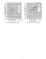
Страница 32: ...Fig 34 Cooling Charging Chart 551B060 Fig 35 Cooling Chart Chart 551B072 32 ...

Страница 33: ...triction in refrigerant system Locate restriction and remove Compressor operates continuously Dirty air filter Replace filter Unit undersized for load Decrease load or increase unit size Thermostat set too low Reset thermostat Low refrigerant charge Locate leak repair and recharge Leaking valves in compressor Replace compressor Air in system Reclaim refrigerant evacuate system and recharge Condens...

Страница 34: ... and EC settings and the economizer control board wiring are correct check to ensure that the 24 vac terminal of the SAT has 24 vac white wire If OAT EC and control board are functioning and wired properly and no 24 vac exists check wiring see unit label diagram 2 If supply air temperature is greater than 57 F 24 vac should be found at terminal T2 on the SAT pink wire If 24 vac is not present repl...

Страница 35: ...The motor should drive towards closed If these actions do not occur replace module 4 Disconnect 1 2 Kohm checkout resistor before resuming operation Damper does not close No power to economizer 1 Disconnect power at TR and TR1 Disconnect jumper across P and P1 2 Connect jumper across TR and 1 3 Connect jumper across T1 and T 4 If connected remove enthalpy sensor from terminals SO and Factory insta...

Страница 36: ...e Installation Overview Operating Sequence A large selection of product theory and skills programs is available All programs include a video cassette and or slides and a companion booklet Use these for self teaching or to conduct full training sessions For a free Service Training Material Catalog STM call 1 800 962 9212 Ordering instructions are included Copyright 1995 Carrier Corporation CATALOG ...

Страница 37: ......

Страница 38: ......

Страница 39: ......

Страница 40: ...AND PROPELLER FOR LOCATION IN HOUSING ORIFICE AND SETSCREW TIGHTNESS M CHECK PULLEY ALIGNMENT AND BELT TENSION PER TO INSTALLATION INSTRUCTIONS III START UP ELECTRICAL SUPPLY VOLTAGE L1 L2 L2 L3 L3 L1 COMPRESSOR AMPS L1 L2 L3 INDOOR FAN AMPS TEMPERATURES OUTDOOR AIR TEMPERATURE DB RETURN AIR TEMPERATURE DB WB COOLING SUPPLY AIR DB PRESSURES REFRIGERANT SUCTION PSIG REFRIGERANT DISCHARGE PSIG M VER...

Отзывы: