


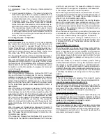


c. Connect T and T1 to the 24 V power supply.
d. After installation is complete, calculate the mini-
mum airflow across the economizer. To calculate the
minimum airflow, the following data is needed: total
cfm (cfm
3
), temperature of the total cfm (T
3
), tem-
perature of the return air (T
2
), and temperature of
the entering outside air (T
1
). Cfm
1
is the outside air
cfm, which will be the minimum airflow.
T
1
(cfm
1
) + T
2
(cfm
2
)
= T
3
cfm
3
cfm
2
= (cfm
3
– cfm
1
)
Therefore:
T
1
(cfm
1
) + T
2
(cfm
3
– cfm
1
)
= T
3
cfm
3
Use this equation to determine cfm
1
, which is the mini-
mum airflow across the economizer.
(T
3
– T
2
) cfm
3
cfm
1
=
(T
1
– T
2
)
If cfm
1
does not match the desired minimum air-
flow from Step 1, re-adjust the minimum position set-
ting screw.
MINIMUM
POSITION
OPEN
3
1
T
P
P1
T1
4
2
5
S
S
O
D
C
TR
B
REV
. B
198818A
%
H
U
M
I
D
I
T
Y
90
70
60
30
10
D
C
B
A
60
65
70
75
55
50
85
80
DAMPER
DAMPER
CLOSED
OPEN
OUTDOOR TEMP
.
°
F
REV.
97-3672
CW–SETPOINTS–CCW
CONT
A
CTS SHO
WN IN HIGH ENTHALPY
RUSH A
T
24V
AC
3 mA
MIN.
A
T
1
1
VDC
CONT
ACT RA
TINGS: 1.5A
RUN, 3.5A
IN
OR UNPOWERED ST
A
T
E
1
2
3
TR
TR1
24V
AC
ENTHALPY
CONTROL
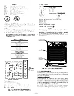
Fig. 18 — Outdoor-Air Thermostat/
Enthalpy Control Installation
LEGEND
OAT — Outdoor-Air Thermostat
NOTE: See unit wiring diagram for more details.
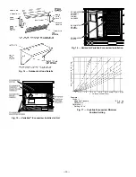
Fig. 19 — Wiring Connections for Outdoor-Air Thermostat
Fig. 20 — Varislide™ Economizer Barometric Relief
Damper Characteristics
—15—
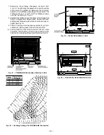
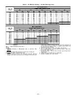
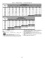
Содержание 551B Series
Страница 32: ...Fig 34 Cooling Charging Chart 551B060 Fig 35 Cooling Chart Chart 551B072 32 ...
Страница 37: ......
Страница 38: ......
Страница 39: ......


