background image

3-50

Confidential

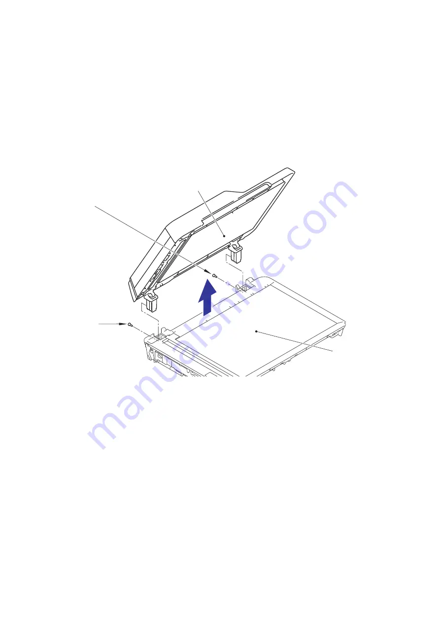
(5) Turn the Document scanner unit right side up.
(6) Remove the two screws (TAPTITE BIND B M4x12) from the Document scanner unit.
(7) Open the ADF unit fully.

Note:

 Lifting up the ASSY without fully opening it in step (8) opens the ADF hinge 

suddenly and unexpectedly with great force. It is DANGEROUS!

Hinweis: 

Das Anheben der Baugruppe, ohne sie zuvor vollständig geöffnet zu haben, 
führt in Schritt (8) dazu, dass der Scharnierarm L plötzlich und unerwartet mit 
großer Kraft nach oben schnellt. Dies ist GEFÄHRLICH!

(8) Remove the ADF unit from the Document scanner unit.

Fig. 3-40

TAPTITE BIND B M4x12

TAPTITE BIND 
B M4x12

ADF unit

Document scanner 

unit

Содержание MFC-J6920DW

Страница 1: ...0 MFC J6520DW J6720DW MFC J6920DW J6925DW Brother Inkjet MFC SERVICE MANUAL June 2013 SM FAX145 8CAT 5 Read this manual thoroughly before maintenance work Keep this manual in a convenient place for quick and easy reference at all times ...

Страница 2: ...i Fi Wi Fi Alliance and Wi Fi Protected Access are registered trademarks of the Wi Fi Alliance FLICKER is a registered trademark of Yahoo Inc Google Cloud Print Google Drive and Picasa Web Albums are trademarks of Google Inc Use of these trademarks are subject to Google Permissions Firefox is a registered trademark of the Mozilla Foundation UNIX is a registered trademark of The Open Group in the U...

Страница 3: ...onal comparison between the models covered by this manual MFC J3520 MFC J3720 MFC J6520DW MFC J6720DW MFC J6920DW J6925DW LCD 2 7 inch 2 7 inch 2 7 inch 2 7 inch 3 7 inch Duplex scan NFC Main PCB B57U184 B57U184 B57U184 B57U184 B57U184 Lower Tray ...

Страница 4: ... 7 Others 1 3 2 FAX 1 4 3 PRINTER 1 4 4 COPY 1 4 5 SCANNER 1 5 6 SOFTWARE 1 5 7 NETWORK 1 5 7 1 Network 1 5 7 2 Wired 1 5 7 3 Wireless 1 5 8 SUPPRIES OPTIONS 1 6 9 SERVICE INFORMATION 1 6 10 PAPER 1 7 10 1 Paper 1 7 10 2 Printable Area 1 10 CHAPTER 2 TROUBLESHOOTING 2 1 1 INTRODUCTION 2 1 1 1 See Precautions for Troubleshooting and or Disassembly Assembly at the end of SAFETY INFORMATION 2 1 1 2 I...

Страница 5: ... 2 Paper is not fed from manual feed slot 2 55 4 2 3 Two or more sheets of paper fed at a time 2 56 4 2 4 Paper feeding at an angle 2 56 4 2 5 Recording paper jam 2 57 4 2 6 Prints only single side of the paper when duplex printing 2 60 4 3 Print image Problems 2 61 4 3 1 Defective images 2 61 4 3 2 Print image problems 2 62 4 4 Software related Problems 2 72 4 4 1 Cannot print data 2 72 4 5 Netwo...

Страница 6: ... PictBridge does not read 2 85 4 10 4 Internal memory errors 2 86 4 10 5 Security Function Lock related problems 2 86 4 10 6 Ink cartridge related problems 2 86 4 10 7 Loud printing sound 2 86 CHAPTER 3 DISASSEMBLY AND ASSEMBLY 3 1 1 PRECAUTIONS BEFORE PROCEEDING 3 1 2 PACKING 3 3 3 SCREW CATALOGUE 3 4 4 SCREW TORQUE LIST 3 5 5 LUBRICATION 3 6 6 OVERVIEW OF GEARS 3 11 7 ROUTING OF HARNESSES AND IN...

Страница 7: ...66 9 20 Document Detection Sensor Document Width Sensor PCB 3 67 9 21 First Side CIS Unit 3 68 9 22 First Side CIS Flat Cable and FFC Film 3 70 9 23 Front Cover L 3 73 9 24 Inner Media Cover 3 74 9 25 Panel ASSY 3 76 9 26 LCD PCB ASSY 3 78 9 27 LCD 3 80 9 28 Touch Panel ASSY 3 80 9 29 NFC PCB 3 81 9 30 Ink Cartridge Cover 3 81 9 31 Lower Side Cover L 3 82 9 32 Lower Side Cover R 3 82 9 33 Upper Si...

Страница 8: ...ER 4 ADJUSTMENTS AND UPDATING OF SETTINGS REQUIRED AFTER PARTS REPLACEMENT 4 1 1 IF YOU REPLACE THE MAIN PCB ASSY 4 1 1 1 Customize destinations Maintenance mode 74 4 3 1 2 Set the CIS type Maintenance mode 59 4 3 1 3 Install the firmware Maintenance mode 28 4 3 1 4 Initialize the EEPROM parameters Maintenance mode 01 4 5 1 5 Restore the head calibration data Maintenance mode 68 4 5 1 6 Set the se...

Страница 9: ... the ADF unit on simplex scanning models 4 18 3 2 Acquisition of white black level data Maintenance mode 55 Not required after replacement of the ADF unit on simplex scanning models 4 18 3 3 Check scanning 4 18 4 IF YOU REPLACE THE PANEL ASSY TOUCH PANEL LCD UNIT OR LCD PCB ASSY 4 19 4 1 Adjust the touch panel Maintenance mode 78 Not required after replacement of the LCD unit 4 19 4 2 Check LCD op...

Страница 10: ...nance mode 17 5 20 1 3 10 Updating of Firmware Using an External Memory Maintenance mode 28 5 21 1 3 11 Sensor Operational Check Maintenance mode 32 5 22 1 3 12 Printout of Dial Log Maintenance mode 37 5 24 1 3 13 Backup of Machine Information Maintenance mode 46 5 25 1 3 14 Setting of Country Language Maintenance mode 52 5 27 1 3 15 Transfer of Received FAX Data and or Equipment s Log Maintenance...

Страница 11: ...58 1 3 33 Equipment Error Code Indication Maintenance mode 82 5 62 1 3 34 Output of Transmission Log to the Telephone Line Maintenance mode 87 5 62 1 3 35 Assurance Mode Switch Setting Maintenance mode 88 5 63 2 OTHER SERVICE FUNCTIONS 5 73 2 1 Displaying the Firmware Version 5 73 2 2 Moving the Head Carriage Unit 5 73 2 3 Retrieving the Equipment Log Information 5 74 CHAPTER 6 CIRCUIT DIAGRAMS AN...

Страница 12: ...ar plug is provided with this product It is designed to be connected to a compatible modular jack that is also compliant See installation instructions for details The REN is used to determine the number of devices that may be connected to a telephone line Excessive RENs on a telephone line may result in the devices not ringing in response to an incoming call In most but not all areas the sum of RE...

Страница 13: ...not installed and used in accordance with the instructions may cause harmful interference to radio communications However there is no guarantee that interference will not occur in a particular installation if this equipment does cause harmful interference to radio or television reception which can be determined by turning the equipment off and on the user is encouraged to try to correct the interf...

Страница 14: ...er Equivalence Number is an indication of the maximum number of devices allowed to be connected to a telephone interface The termination on an interface may consist of any combination of devices subject only to the requirement that the sum of the RENs of all the devices does not exceed five L indice d équivalence de la sonnerie IES sert à indiquer le nombre maximal de terminaux qui peuvent être ra...

Страница 15: ... click Download Your Declaration will be downloaded as a PDF file Declaration of Conformity for R TTE Radio and Telecommunications Directive 1999 5 EC Europe only Applicable to models with telecommunications and or radio interfaces We Brother Industries Ltd 15 1 Naeshiro cho Mizuho ku Nagoya 467 8561 Japan declare that these products are in conformity with the provisions of the R TTE Directive 199...

Страница 16: ...s It indicates that at the end of the life of the product battery you should dispose of it separately at an appropriate collection point and not place it in the normal domestic waste stream International ENERGY STAR Qualification Statement The purpose of the International ENERGY STAR Program is to promote the development and popularization of energy efficient equipment As an ENERGY STAR Partner Br...

Страница 17: ...ially hazardous situation which if not avoided may result in damage to property or loss of product functionality Prohibition icons indicate actions that must not be performed This icon indicates that flammable sprays must not be used This icon indicates that organic solvents such as alcohol and liquids must not be used Electrical Hazard icons alert you to possible electrical shocks Fire Hazard ico...

Страница 18: ...unplugged the power cord from the AC power outlet as well as any telephone RJ 11 or Ethernet RJ45 cables from the machine DO NOT push objects of any kind into this machine through slots or openings in the cabinet as they may touch dangerous voltage points or short out parts DO NOT handle the plug with wet hands Always make sure the plug is fully inserted DO NOT continue using the machine if it has...

Страница 19: ...commends that you DO NOT use any type of extension cord DO NOT use this product during an electrical storm Never touch telephone wires or terminals that are not insulated unless the telephone line has been unplugged at the wall jack Never install telephone wiring during a lightning storm Never install a telephone wall jack in a wet location FIRE HAZARDS Failure to follow the warnings in this secti...

Страница 20: ...up Failure to do this may cause injury to your fingers by trapping them in a roller If the tray has been expanded to hold large paper such as Ledger A3 or Legal size paper position the machine so that the tray will not protrude past the edge of the table or desk When the tray is expanded it will protrude from the machine Therefore if someone hits the tray the machine could fall and cause injury DO...

Страница 21: ...egal size to the original size be careful not to pinch your fingers in the gaps or slots in the bottom of the tray It may cause injury to you DO NOT touch the area shaded in the illustration Doing this may cause injury to your fingers by cutting them on the edge of the machine ...

Страница 22: ... by sliding your hands into the hand hold indentations located on each side of the machine MFC J3720 J6720DW J6920DW and MFC J6925DW only To prevent injuries when moving or lifting this machine make sure to use at least two people Be careful not to pinch your fingers when you set the machine back down DO NOT carry the machine by holding the lower tray when it is installed The lower tray could fall...

Страница 23: ...ower tray to fall and cause injury to you Do not remove the serial number and instruction labels that are affixed to the machine IMPORTANT Disruption of power can wipe out information in the machine s memory DO NOT put objects on top of the machine DO NOT place anything in front of the machine that will block received faxes DO NOT place anything in the path of received faxes MFC J6520DW ...

Страница 24: ...0 Static electricity charged in your body may damage electronic parts Before handling the PCBs touch a metal portion of the machine to discharge static electricity charged in your body When transporting PCBs be sure to wrap them in conductive sheets When replacing the PCBs put on a grounding wrist band and perform the job on a conductive mat Also take care not to touch the conductor sections on th...

Страница 25: ... Landscape A4 LTR Portrait A3 LGR B4 LGL N A Landscape A4 LTR Portrait A3 LGR LGL Manual Feed Slot Landscape A4 LTR EXE B5 Portrait A3 LGR B4 LGL Folio A5 A6 Photo 102 x 152 mm 4 x 6 Indexcard 127 x 203 mm 5 x 8 Photo L 89 x 127 mm 3 5 x 5 Photo 2L 127 x 178 mm 5 x 7 C5 Com 10 DL Envelope Monarch Duplex Print PC Print A3 LGR B4 LGL Folio A4 LTR EXE A5 B5 Copy A3 LGR B4 LGL A4 LTR A5 ADF width leng...

Страница 26: ...J6520DW MFC J6720DW MFC J6920DW J6925DW Memory Capacity physical Mbytes 128 MB 256 MB Memory Backup with Flash memory Yes Model MFC J3520 MFC J3720 MFC J6520DW MFC J6720DW MFC J6920DW J6925DW Host Interface Hi Speed USB 2 0 LAN Yes Wireless LAN Yes NFC N A Yes PictBridge Yes USB Memory Yes Acceptable Media Cards Type Size Media Card Memory Stick Duo 16 MB 128 MB Memory Stick Pro Pro Duo Micro 256 ...

Страница 27: ... w 4 5 w 1 5 w 0 04 w 30 w 5 0 w 1 5 w 0 04 w Europe 28 w 5 5 w 1 5 w 0 04 w 29 w 5 5 w 1 5 w 0 04 w Asia Oceania 28 w 5 5 w 1 5 w 0 04 w 29 w 5 5 w 1 5 w 0 04 w China 28 w 5 5 w 1 5 w 0 04 w N A Machine Noise Operating 50 dBA Maximum Machine Dimensions W553 x D433 x H247 mm W553 x D433 x H310 mm W553 x D433 x H247 mm W553 x D433 x H310 mm Machine Weight U S A N A 14 3 kg 31 5 lb 16 5 kg 36 4 lb E...

Страница 28: ... based on ISO IEC 24734 22 20 ipm Draft Print Speed mono color time calculated including paper feeding 35 27 ppm Resolution horizontal x vertical Up to 1 200 x 6 000 dpi Auto Duplex Print Yes Up to A3 LGR Model All models COPY SPEED ESAT mono color based on ISO IEC 24735 12 9 ipm COPY SPEED FCOT based on ISO IEC 24735 Annex D 18 sec Resolution horizontal x vertical Mono Print Max 1 200 x 2 400 dpi...

Страница 29: ... Windows 8 Up to 19 200 x 19 200 dpi with Scanner Utility Model All models Driver Support OS Version Windows Windows XP XP x64 Vista 7 8 8 1 Windows Server 2003 2003 R2 2008 2008 R2 2012 2012 R2 Macintosh Mac OS X v10 6 8 10 7 x 10 8 x Model All models Internet FAX Firmware versionT37 Yes Download Model All models Model Name Ethernet Embedded NC 320h Network Connection Ethernet Ethernet 10 100BASE...

Страница 30: ...ld Cartridges BK 2 400 CL 1 200 Storage Condition of Ink Cartridge Temperature Normal condition 20 to 40 C Humidity Normal condition 20 to 80 Storage condition at the temperature of 40 to 50 C and the humidity of 80 to 95 Up to 5 days Storage condition at the temperature of 40 to 60 C and the humidity of Non controll condition Up to 5 days Model All models Monthly Volume 26 000 pages Machine Life ...

Страница 31: ...2 x 10 1 inch 182 x 257 mm User Defined A5 5 8 x 8 3 inch 148 x 210 mm Yes Yes A6 4 1x 5 8 inch 105 x 148 mm Yes Cards Photo 4 x 6 inch 10 x 15 cm Yes Yes Yes Photo L 3 1 2 x 5 inch 89 x 127 mm Yes Photo 2L 5 x 7 inch 13 x 18 cm Yes Yes Index Card 5 x 8 inch 127 x 203 mm Yes Postcard 1 3 9 x 5 8 inch 100 x 148 mm User Defined Postcard 2 Double 5 8 x 7 9 inch 148 x 200 mm User Defined Envelopes C5 ...

Страница 32: ...Up to 0 25 mm Cards Photo 4 x 6 Card 1 Up to 58 lb Up to 220 g m2 Up to 10 mil Up to 0 25 mm Index Card Up to 32 lb Up to 120 g m2 Up to 6 mil Up to 0 15 mm Postcard 1 Postcard 2 Up to 53 lb Up to 200 g m2 Up to 10 mil Up to 0 25 mm Envelopes 20 to 25 lb 80 to 95 g m2 Up to 20 mil Up to 0 52 mm Transparencies Paper size Paper types Standard Tray Landscape Letter Executive A4 Portrait Ledger A3 Leg...

Страница 33: ... water and perspiration easily and this may cause decreased output quality Transparencies designed for laser printers copier may stain your next document Use only transparencies recommended for inkjet printing IMPORTANT DO NOT use the following kinds of paper Damaged curled wrinkled or irregularly shaped paper 1 0 08 inch 2mm or greater curl may cause jams to occur Extremely shiny or highly textur...

Страница 34: ...nt in the shaded areas of cut sheet paper only when the Borderless print feature is available and turned on Note The Borderless print feature is not available for envelopes and 2 sided printing Top 1 Left 2 Bottom 3 Right 4 Cut Sheet 0 12 inch 3 mm 0 12 inch 3 mm 0 12 inch 3 mm 0 12 inch 3 mm Envelopes 0 87 inch 22 mm 0 12 inch 3 mm 0 87 inch 22 mm 0 12 inch 3 mm 1 3 4 2 1 3 4 2 Cut Sheet Paper En...

Страница 35: ... not exposed to direct sunlight excessive heat moisture or dust 4 The machine is transported in level Power requirements 1 The power requirements described in label of the machine is supplied Its variation is within 10 of the rated voltage 2 All cables and harnesses are firmly connected 3 The fuses are not blown Recording paper 1 A recommended type of paper is being used refer to Chapter 1 Section...

Страница 36: ...Confidential 2 2 Cleaning Use a soft dry lint free cloth DO NOT use flammable solvent such as alcohol benzine thinner to clean the body of the machine DO NOT use near by WARNING WARNING ...

Страница 37: ...ller1 First side document pressure bar First side CIS unit scanning position First side document Document ejection roller Document width actuator Document detection actuator ADF separation pad actuator Second side CIS unit feed roller2 Second side document scanning position actuator Document tray Duplex scanning models only Duplex scanning models only Duplex scanning models only Duplex scanning mo...

Страница 38: ...ead carriage unit Manual feed slot Bank ASSY T2 paper pull in roller T1 paper pull in roller Lower tray Duplex paper feed roller Switchback roller Panel ASSY Switchback actuator Paper ejection roller Platen Paper feed roller Registration actuator ...

Страница 39: ...ing Path 2 2 1 Document Feeding Path Fig 2 3 2 2 2 Recording Paper Feeding Path Fig 2 4 Document feeding path during ADF scanning Feeding path during duplex printing Feeding path from the manual feed slot Feeding path from paper tray 1 Feeding path from lower tray ...

Страница 40: ...le sheet Document feed roller1 This feeds a document to the second side CIS unit Document feed roller2 This feeds a document to the first side CIS unit Second side document scanning position actuator This detects the leading edge of document pages indicating the scanning start position of the second side Only in the case of duplex scanning This detects paper jamming in the ADF First side document ...

Страница 41: ...er Switchback actuator This detects whether the printed recording papers are ejected This detects the ending edge of recording paper after printing the first side when duplex printing adjusting timing to reverse the switchback roller rotation This detect the leading edge ending edge of recording paper when duplex printing identifying the recording paper size This detects whether the recording pape...

Страница 42: ...LAN PHY LAN MAC PC Wireless LAN PCB AFE LED Driver Paper feed motor SDAA Ink cartridge PCB Ink cartridge IC chip RMII Modem AMP Ethernet Panel PCB Control panel Power key LCD Touch panel LCD PCB ASSY First side document scanning position sensor ADF cover sensor ADF motor Document scanner motor Documentscannersensor PF encoder sensor Registration sensor PCB Registration sensor Purge cam sensor Swit...

Страница 43: ... cover sensor ASSY Ink absorber box Ink cartridge cover Power supply PCB ASSY PF encoder registration sensor harness PF encoder sensor PCB ASSY Flushing box Registration sensor PCB ASSY Document scanner unit Manual feed slot cover ASSY Paper tray 1 Lower power supply frame PF encoder disk Inner chute ASSY Paper feed roller Paper feed motor Platen foam Paper ejection Platen CR timing belt CR encode...

Страница 44: ...h is longer than 245 9 mm detection by registration sensor switchback sensor Paper length is shorter than 143 5 mm detection by registration sensor switchback sensor 2 22 18 Paper jam during duplex printing Registration sensor does not detect paper feed within specified pulse numbers in the second side paper re feed 2 23 20 Cannot identify a black ink cartridge The ink cartridge detection sensor a...

Страница 45: ...dge detection sensor 2 27 2C No cyan ink cartridge loaded detected by the ink cartridge detection sensor 2 27 2D No magenta ink cartridge loaded detected by the ink cartridge detection sensor 2 27 2E Cannot communicate with ink cartridge IC chip machine body side 2 27 2F Ink cartridge cover sensor detects opened cover state 2 28 30 Head carriage unit does not move Detected by the CR encoder sensor...

Страница 46: ...tenance unit stopped abnormally during exhaustion suction 2 38 5D Excessive current protection activated for the driver IC during purge cam operation 2 38 5E Excessive current protection activated for the driver IC during pump operation 2 38 67 Switchback sensor detects no paper tray 1 state 2 39 75 Head carriage unit cannot shift to head capping position 2 39 76 Head carriage unit cannot shift to...

Страница 47: ...ent scanning position sensor cannot detect document within specified time 2 46 A4 ADF cover sensor detects opened cover state 2 46 A5 Level of first side CIS scan result is detected as abnormal during FAX transmission first transmission 2 47 A6 Level of first side CIS scan result is detected as abnormal during FAX transmission after re try 2 47 A7 Type of CIS unit and CIS type input value does not...

Страница 48: ...EEPROM write error 2 51 E9 NFC PCB initialization failed 2 51 EC LCD disconnection detected 2 52 ED Touch panel initialization failed 2 52 F0 Flash file system error 2 52 F8 Battery harness is detected to be not correctly inserted 2 53 FE ROM data acquisition error 2 53 ...

Страница 49: ...t make the polling setting Cover is Open Document scanner sensor detects that document scanner is open A1 2 45 ADF cover sensor detects opened cover state A4 2 46 Ink cartridge cover sensor detects opened cover state 2F 2 28 Data Remaining in Memory Data cannot be processed due to memory full Disconnected Destination fax machine stops Document Jam Document scanning position sensor detects paper ja...

Страница 50: ...n the memory by the Memory Receive function exceeds the upper limit Out of Memory Memory is insufficient Paper Jam Registration sensor switchback sensor and paper width sensor detect paper jam Some kind of error occurs on the paper feed motor 13 15 18 31 38 3C 82 84 87 88 8A 8C 2 21 2 23 2 29 2 30 2 31 2 41 2 42 2 43 2 44 Paper tray not detected Switchback sensor detects no paper tray 1 67 2 39 To...

Страница 51: ...se after sending Fax2 net command 13 12 NG response signal is received after sending Fax2 net command 17 07 No response from the calling station in receiving 20 01 Unable to detect a flag field 20 02 Carrier termination lasts for 200 msec 20 03 Termination command consecutive 1 of 7 bits or more 20 04 Overrun detected 20 05 A frame for 3 seconds or more received 20 06 CRC error in answerback 20 07...

Страница 52: ...te terminal not equipped with SUB function 32 18 Remote terminal not equipped with color function 40 02 Illegal coding system requested 40 03 Illegal recording width requested 40 05 ECM requested although not allowed 40 06 Polled while not ready 40 07 No document to send when polled 40 08 There is no data in the box No specified by F code communication 40 10 Nation code or manufacturer code not co...

Страница 53: ...rieval of confidential data using F code 63 12 Password specified by F code does not match 74 XX DCN received 80 01 Fallback impossible 90 01 Unable to detect video signals or commands within 6 seconds after CFR is transmitted 90 02 Received PPS containing invalid page count or block count A0 03 Error correction sequence not terminated even at the final transmission speed for fallback A0 11 Receiv...

Страница 54: ...essing X key after confirming FAX communication C0 01 No common modulation mode or polling failed C0 02 Unable to detect JM C0 03 Unable to detect CM C0 04 Unable to detect CJ C0 10 V 34 negotiation or training not finished C0 11 Modem error detected during V 34 negotiation or training C0 20 Modem error detected during sending of commands C0 21 Modem error detected during receiving of commands C0 ...

Страница 55: ...heck Remove the jammed paper Check whether the recording paper being used is within the specification Firmly set the paper tray to the rear end Paper Jam LCD Step Cause Solution 1 Switchback actuator caught on the surrounding parts Set the switchback frame ASSY into place 2 Registration actuator caught on the surrounding parts Set the registration actuator into place 3 Registration sensor defectiv...

Страница 56: ...g Paper Size Wrong Paper LCD Step Cause Solution 1 CR encoder strip stained Clean the CR encoder strip 2 Registration actuator caught on the surrounding parts Set the registration actuator into place 3 PF encoder disk stained Clean the PF encoder disk and flushing guide refer to Chapter 3 Section 1 PRECAUTIONS BEFORE PROCEEDING 4 Switchback actuator caught on the surrounding parts Set the switchba...

Страница 57: ...jammed paper Check whether the recording paper being used is within the specification Check that recording paper are not curled wrinkled or wet Paper Jam LCD Step Cause Solution 1 Foreign materials in the duplex print paper path Remove foreign materials 2 Registration actuator caught on the surrounding parts Set the registration actuator into place 3 Registration sensor defective Replace the regis...

Страница 58: ...ng sensor are detecting Error Code 23 Cannot identify a magenta ink cartridge The ink cartridge detection sensor and the ink remaining sensor are detecting User Check Check if incompatible ink cartridge is loaded Reload the ink cartridge Replace the ink cartridge Check if ink cartridge has been already set before instruction for ink cartridge setting during initial installation Cannot Detect LCD C...

Страница 59: ...artridge at position for correct color Set starter ink cartridge Error Code 25 Cannot communicate with ink cartridge IC chip ink cartridge side User Check Check if incompatible ink cartridge is loaded Reload the ink cartridge Replace the ink cartridge Cannot Detect Wrong Color Ink LCD Install Starter Ink LCD Step Cause Solution 1 Main PCB defective Replace the main PCB ASSY Cannot Detect LCD Step ...

Страница 60: ...by the ink remaining sensor ink discharged for specified times Error Code 29 Magenta ink cartridge reaches service life time After judging as no ink by the ink remaining sensor ink discharged for specified times User Check Replace the ink cartridge Cannot Print Replace Ink LCD Cannot Print Replace Ink B W 1 sided Print Only Replace Ink LCD Cannot Print Replace Ink B W 1 sided Print Only Replace In...

Страница 61: ... detection sensor User Check Check if incompatible ink cartridge is loaded Reload the ink cartridge Replace the ink cartridge Error Code 2E Cannot communicate with ink cartridge IC chip machine body side Cannot Print No Ink Cartridge LCD Cannot Print No Ink Cartridge LCD Cannot Print No Ink Cartridge LCD Cannot Print No Ink Cartridge LCD Step Cause Solution 1 Ink cartridge detection sensor defecti...

Страница 62: ...fective Replace the main PCB ASSY Unable to Print 30 LCD Step Cause Solution 1 Foreign materials in the engine unit Remove foreign materials 2 CR encoder strip out of place Set the CR encoder strip into place 3 CR timing belt out of place Set the CR timing belt into place 4 Head cover out of place Set the Head cover into place 5 Carriage motor harness connection failure Reconnect the carriage moto...

Страница 63: ...der strip 5 Flushing box not mounted in place Set the flushing box into place 6 Carriage rail not mounted in place Set the carriage rail into place 7 Platen not mounted in place Set the platen into place 8 Maintenance unit not mounted in place Set the maintenance unit into place 9 CR encoder sensor defective Replace the carriage PCB ASSY 10 Maintenance unit defective Replace the maintenance unit 1...

Страница 64: ...er strip stained Clean the CR encoder strip 3 Switching lever guide out of place Set the switching lever guide into place 4 CR encoder strip defective Replace the CR encoder strip 5 CR encoder sensor defective Replace the carriage PCB ASSY 6 Main PCB defective Replace the main PCB ASSY Paper Jam LCD Step Cause Solution 1 Foreign materials in the engine unit Remove foreign materials 2 CR encoder st...

Страница 65: ...eign materials 2 CR encoder strip stained Clean the CR encoder strip 3 Switching lever guide out of place Set the switching lever guide into place 4 CR encoder strip defective Replace the CR encoder strip 5 CR encoder sensor defective Replace the carriage PCB ASSY 6 Main PCB defective Replace the main PCB ASSY Paper Jam LCD Step Cause Solution 1 Foreign materials in the engine unit Remove foreign ...

Страница 66: ...oreign materials in the engine unit Remove foreign materials 6 Maintenance unit not mounted in place Set the maintenance unit into place 7 Flushing box not mounted in place Set the flushing box into place 8 Carriage rail not mounted in place Set the carriage rail into place 9 Platen not mounted in place Set the platen into place 10 PF encoder sensor defective Replace the PF encoder sensor PCB ASSY...

Страница 67: ...place the CR encoder strip 4 CR encoder sensor defective Replace the carriage PCB ASSY 5 Carriage motor defective Replace the carriage motor ASSY 6 Main PCB defective Replace the main PCB ASSY Unable to Print 40 LCD Step Cause Solution 1 Casing internal thermistor defective Replace the ink cartridge PCB ASSY 2 Main PCB defective Replace the main PCB ASSY Unable to Print 42 LCD Step Cause Solution ...

Страница 68: ...tive Replace the main PCB ASSY Unable to Print 44 LCD Step Cause Solution 1 Carriage flat cable connection failure Reconnect the carriage flat cable 2 Head property information not input Input the head property information refer to Chapter 5 Section 1 3 25 Updating of Head Property Data and Backup Restoration of Head Calibration Data 3 Head defective Replace the head carriage unit 4 Main PCB defec...

Страница 69: ...Reconnect the carriage flat cable 3 Carriage PCB defective Replace the carriage PCB ASSY 4 Head defective Replace the head carriage unit 5 Main PCB defective Replace the main PCB ASSY Unable to Print 49 LCD Step Cause Solution 1 Head flat cable connection failure Reconnect the head flat cable 2 Carriage flat cable connection failure Reconnect the carriage flat cable 3 Carriage PCB defective Replac...

Страница 70: ...t cable 3 Carriage PCB defective Replace the carriage PCB ASSY 4 Head defective Replace the head carriage unit 5 Power supply PCB defective Replace the power supply PCB ASSY 6 Main PCB defective Replace the main PCB ASSY Unable to Print 50 LCD Step Cause Solution 1 Foreign materials in the maintenance unit Remove foreign materials 2 Purge cam switch harness connection failure Reconnect the purge c...

Страница 71: ...gn materials in the maintenance unit Remove foreign materials 2 Purge cam switch harness connection failure Reconnect the purge cam switch harness 3 Paper feed motor defective Replace the paper feed motor 4 PF encoder sensor defective Replace the PF encoder sensor PCB ASSY 5 Maintenance unit defective Replace the maintenance unit 6 Main PCB defective Replace the main PCB ASSY ...

Страница 72: ...ble to Print 5B LCD Unable to Print 5D LCD Unable to Print 5E LCD Step Cause Solution 1 Foreign materials in the maintenance unit Remove foreign materials 2 PF encoder disk stained Clean the PF encoder disk and flushing guide refer to Chapter 3 Section 1 PRECAUTIONS BEFORE PROCEEDING 3 PF encoder disk defective Replace the PF encoder disk 4 PF encoder sensor defective Replace the PF encoder sensor...

Страница 73: ...itchback sensor harness connection failure Reconnect the switchback sensor harness 3 Outer paper guide wear defective Replace the outer paper guide 4 Paper tray 1 defective Replace the paper tray 1 5 Main PCB defective Replace the main PCB ASSY Unable to Print 75 LCD Unable to Print 76 LCD Step Cause Solution 1 CR encoder strip out of place Set the CR encoder strip into place 2 Foreign materials i...

Страница 74: ...SY Wrong Paper Size Wrong Paper LCD Step Cause Solution 1 Registration actuator caught on the surrounding parts Set the registration actuator into place 2 CR encoder strip stained Clean the CR encoder strip 3 PF encoder disk stained Clean the PF encoder disk and flushing guide refer to Chapter 3 Section 1 PRECAUTIONS BEFORE PROCEEDING 4 CR encoder strip defective Replace the CR encoder strip 5 PF ...

Страница 75: ...ve the jammed paper in jam clear cover part Wrong Paper Size Wrong Paper LCD Step Cause Solution 1 CR encoder strip stained Clean the CR encoder strip 2 CR encoder strip defective Replace the CR encoder strip 3 Paper width sensor defective Replace the carriage PCB ASSY 4 Carriage motor defective Replace the carriage motor ASSY 5 Main PCB defective Replace the main PCB ASSY Paper Jam LCD Step Cause...

Страница 76: ...hback actuator caught on the surrounding parts Set the switchback frame ASSY into place 4 Paper feed roller paper ejection roller switchback roller stained Clean the related rollers 5 Paper feed roller paper ejection roller switchback roller defective Replace related rollers 6 Main PCB defective Replace the main PCB ASSY Paper Jam LCD Step Cause Solution 1 Foreign materials in the feeding path Rem...

Страница 77: ...tained Clean the related rollers 5 Paper feed roller paper ejection roller defective Replace related rollers 6 Main PCB defective Replace the main PCB ASSY Unable to Print 89 LCD Step Cause Solution 1 PF encoder disk stained Clean the PF encoder disk and flushing guide refer to Chapter 3 Section 1 PRECAUTIONS BEFORE PROCEEDING 2 PF home position detection lever stained Clean the PF home position d...

Страница 78: ...tion failure Reconnect the paper feed motor harness 3 PF encoder sensor harness connection defective Reconnect the PF encoder sensor harness 4 PF roller belt out of place Set the PF roller belt into place 5 PF encoder sensor defective Replace the PF encoder sensor PCB ASSY 6 PF encoder disk defective Replace the PF encoder disk 7 Paper feed motor defective Replace the paper feed motor 8 Main PCB d...

Страница 79: ... belt out of place Set the paper feed roller belt into place 3 Main PCB defective Replace the main PCB ASSY Cover is Open LCD Step Cause Solution 1 Document scanner actuator out of place Set the document scanner actuator into place 2 Document scanner sensor defective Replace the document scanner sensor 3 Document scanner unit boss broken Replace the document scanner unit 4 Main PCB defective Repla...

Страница 80: ...cument scanning position actuator out of place Set the document scanning position actuator into place 4 Document scanning position sensor harness connection failure Reconnect the document scanning position sensor harness 5 Document scanning position sensor defective Replace the document scanning position sensor PCB ASSY 6 Document pick up roller worn out Replace the document separation roller ASSY...

Страница 81: ... obtain white level data 2 White reference tape stained Clean document cover glass at white reference tape 3 First side CIS unit defective Replace the first side CIS unit 4 White reference tape damage broken Replace the document scanner unit 5 Main PCB defective Replace the main PCB ASSY Unable to Scan A7 LCD Step Cause Solution 1 First side or second side CIS type input value error Automatically ...

Страница 82: ...n PCB defective Replace the main PCB ASSY Unable to Scan AF LCD Step Cause Solution 1 Scanner belt out of place Set the scanner belt into place 2 Document scanner motor harness connection failure Reconnect the document scanner motor harness 3 First side CIS flat cable connection failure Reconnect the first side CIS flat cable 4 First side CIS flat cable and second side CIS flat cable are connected...

Страница 83: ...DF cover stained Clean the white reference tape of document pressure bar of ADF cover 3 Second side CIS unit defective Replace the second side CIS unit 4 White reference tape of document pressure bar of ADF cover damage broken Replace the ADF cover 5 Main PCB defective Replace the main PCB ASSY Unable to Scan BD LCD Step Cause Solution 1 Black level data failure Carry out maintenance 55 to obtain ...

Страница 84: ... Scan BF LCD Step Cause Solution 1 Document scanning position actuator caught on the surrounding parts Set the document scanning position actuator into place 2 Document scanning position sensor defective Replace the document scanning position sensor 3 Document feed roller worn out ADF motor defective Replace the ADF unit 4 Main PCB defective Replace the main PCB ASSY Unable to Print DF LCD Unable ...

Страница 85: ...se Solution 1 Wireless LAN PCB ASSY connection failure Reconnect the wireless LAN PCB ASSY 2 Wireless LAN PCB defective Replace the wireless LAN PCB ASSY 3 Main PCB defective Replace the main PCB ASSY Unable to Print E6 LCD Step Cause Solution 1 Main PCB defective Replace the main PCB ASSY Unable to Print E9 LCD Step Cause Solution 1 NFC PCB harness connection failure Reconnect the NFC PCB harness...

Страница 86: ...t cable 2 LCD PCB harness connection failure Reconnect the LCD PCB harness 3 LCD PCB ASSY defective Replace the LCD PCB ASSY 4 LCD unit defective Replace the LCD unit 5 Main PCB defective Replace the main PCB ASSY Unable to Print ED LCD Step Cause Solution 1 Touch panel defective Replace the touch panel ASSY 2 LCD PCB ASSY defective Replace the LCD PCB ASSY 3 Main PCB defective Replace the main PC...

Страница 87: ... setting power supply voltage fluctuation or problem of software User Check Turn the power OFF and ON Error Code FE ROM data acquisition error User Check Turn the power OFF and ON Unable to Print F8 LCD Step Cause Solution 1 Main PCB defective Replace the main PCB ASSY Unable to Print FE LCD Step Cause Solution 1 Program malfunctioning Re load the firmware 2 Main PCB defective Replace the main PCB...

Страница 88: ... place Set the paper pull in roller into place 2 CR encoder strip stained Clean the CR encoder strip 3 PF encoder disk stained Clean the PF encoder disk and flushing guide refer to Chapter 3 Section 1 PRECAUTIONS BEFORE PROCEEDING 4 Bank ASSY out of place Set the bank ASSY into place 5 The grease of the switching lever guide of the maintenance unit is not enough Apply the grease for the switching ...

Страница 89: ... Cause Solution 1 Paper feed motor harness connection failure Reconnect the paper feed motor harness 2 Registration actuator out of place Set the registration actuator into place 3 Registration sensor defective Replace the registration sensor PCB ASSY 4 Paper feed motor defective Replace the paper feed motor 5 Main PCB defective Replace the main PCB ASSY Apply grease here Maintenance unit Lubrican...

Страница 90: ...Check Check that recording paper is loaded correctly in the paper tray Adjust the paper guide to match the recording paper size Check thickness of recording paper is within tolerance of each type Check if too much paper is loaded in the paper tray Clean the paper pull in roller Step Cause Solution 1 Bank ASSY worn out Replace the bank ASSY 2 Base pad worn out Replace the base pad Step Cause Soluti...

Страница 91: ...ion 1 Foreign materials in the recording paper path Remove foreign materials 2 Bank ASSY out of place Set the bank ASSY into place 3 Platen foam drift Set the platen foam into place 4 Jam clear cover not mounted in place Set the jam clear cover into place 5 CR guide rail not mounted in place Set the CR guide rail into place 6 Platen not mounted in place Set the platen into place 7 Platen spring no...

Страница 92: ...inner paper guide not mounted in place Set the switchback inner paper guide into place 8 Switchback outer paper guide not mounted in place Set the switchback outer paper guide into place 9 Switchback roller belt out of place Set the switchback roller belt into place 10 Paper eject roller belt out of place Set the paper eject roller belt into place 11 CR guide rail not mounted in place Set the CR g...

Страница 93: ...r paper guide into place 3 Switchback outer paper guide not mounted in place Set the switchback outer paper guide into place 4 Paper eject roller belt out of place Set the paper eject roller belt into place 5 Main PCB defective Replace the main PCB ASSY Step Cause Solution 1 Foreign materials in the recording paper path Remove foreign materials 2 Switchback inner paper guide not mounted in place S...

Страница 94: ...k Set the driver settings to duplex printing Check if the recording papers are not overlapping each other Shuffle the papers thoroughly in the case of overlapping Step Cause Solution 1 Switching lever guide defective Replace the maintenance unit 2 Main PCB defective Replace the main PCB ASSY ...

Страница 95: ...ash Print edges not aligned Random missing dots White horizontal streaks Stained leading edge of recording paper Overlapping lines over the whole page Separated lines over the whole page Overlapping lines at the trailing edge of the recording paper Separated lines at the trailing edge of the recording paper Characters having shadows ghost Traces of paper pull in roller Dirt on the paper ...

Страница 96: ...ead property value refer to Chapter 5 Section 1 3 25 Updating of Head Property Data and Backup Restoration of Head Calibration Data 3 Head flat cable connection failure Reconnect the head flat cable 4 Carriage flat cable connection failure Reconnect the carriage flat cable 5 Non discharge of ink from head Perform the recommended purge procedures refer to the recommended procedures in Chapter 5 Sec...

Страница 97: ... Wrong head property value Input the head property value refer to Chapter 5 Section 1 3 25 Updating of Head Property Data and Backup Restoration of Head Calibration Data 3 Head calibration uncompleted Write the head calibration data refer to Chapter 5 Section 1 3 2 Creating of Head Calibration Data and Writing it into Flash ROM 4 Non discharge of ink from head Perform the recommended purge procedu...

Страница 98: ...er 5 Section 1 3 29 Purge Operation Maintenance mode 76 5 Carriage PCB defective Replace the carriage PCB ASSY 6 Maintenance unit defective Replace the maintenance unit 7 Head defective Replace the head carriage unit 8 Main PCB defective Replace the main PCB ASSY User Check Check whether the paper type setting is correct Step Cause Solution 1 Maintenance unit stained Clean the maintenance unit ref...

Страница 99: ...arriage flat cable into place 5 Ink supply tubes not mounted in place Set the ink supply tubes guide into place 6 CR encoder strip defective Replace the CR encoder strip User Check Carry out head cleaning Step Cause Solution 1 Foreign materials in the carriage rail Remove foreign materials 2 CR encoder strip stained Clean the CR encoder strip 3 Non discharge of ink from head Perform the recommende...

Страница 100: ... whether the recording paper being used is within the specification Perform the printing position adjustment Set the improvement of the ruled line offset of Selector Nos 1 to 3 of AMS07 refer to 1 3 35 Assurance Mode Switch Setting Step Cause Solution 1 Vertical print lines not aligned Adjust vertical print line alignment refer to Chapter 5 Section 1 3 23 Adjustment of Vertical Print Lines Softwar...

Страница 101: ... unit stained Clean the maintenance unit refer to Fig 2 10 2 62 2 Paper feeding correction not updated Update paper feed correction refer to Chapter 5 Section 1 3 19 Updating of Paper Feeding Correction Values 3 Head inclination is not correctly adjusted Adjust the head inclination refer to Chapter 4 Section 2 4 Adjust head inclination 4 PF encoder disk stained Clean the PF encoder disk and flushi...

Страница 102: ...lution 1 Head inclination is not correctly adjusted Adjust the head inclination refer to Chapter 4 Section 2 4 Adjust head inclination 2 Head calibration uncompleted Write the head calibration data refer to Chapter 5 Section 1 3 2 Creating of Head Calibration Data and Writing it into Flash ROM 3 Paper feeding correction value not updated Adjust the paper feeding correction value refer to Chapter 5...

Страница 103: ...coder disk and flushing guide refer to Chapter 3 Section 1 PRECAUTIONS BEFORE PROCEEDING 5 Non discharge of ink from head Perform the recommended purge procedures refer to the recommended procedures in Chapter 5 Section 1 3 29 Purge Operation Maintenance mode 76 6 PF encoder disk defective Replace the PF encoder disk 7 Head defective Replace the head carriage unit 8 Main PCB defective Replace the ...

Страница 104: ...PF encoder disk 5 Main PCB defective Replace the main PCB ASSY User Check Carry out head cleaning Step Cause Solution 1 Paper feeding correction value not updated Adjust the paper feeding correction value refer to Chapter 5 Section 1 3 19 Updating of Paper Feeding Correction Values 2 Vertical print lines not aligned Adjust vertical print line alignment refer to Chapter 5 Section 1 3 23 Adjustment ...

Страница 105: ...ng used is not folded Check whether the recording paper being used is within the specification Clean the related rollers by printing blank paper Clean the platen Step Cause Solution 1 Maintenance unit stained Clean the maintenance unit refer to Fig 2 10 2 62 2 Foreign materials in the reverse side of the head Remove foreign materials 3 Paper feed roller stained Replace the paper feed roller 4 Pape...

Страница 106: ...LAN cable is not broken Check if the correct product is selected if the interface switching device is in use Check the driver settings Reset to the factory default refer to the user s guide 4 5 Network Problems 4 5 1 Cannot make a print through network connection User Check Check items in the network setting guide Carry out network reset refer to the user s guide Step Cause Solution 1 Main PCB def...

Страница 107: ... panel PCB harness 3 LCD PCB ASSY defective Replace the LCD PCB ASSY 4 Panel PCB defective Replace the panel ASSY 5 Power supply PCB and power cord defective Replace the power supply PCB ASSY 6 Main PCB defective Replace the main PCB ASSY Step Cause Solution 1 Panel PCB harness connection failure Reconnect the panel PCB harness 2 Panel PCB defective Replace the panel ASSY 3 Power supply PCB defect...

Страница 108: ...ction actuator into place 4 Document width actuator not mounted in place Set the document width actuator into place 5 ADF motor harness connection failure Reconnect the ADF motor harness 6 Document detection sensor harness connection failure Reconnect the document detection sensor harness 7 Document width sensor harness connection failure Reconnect the document width sensor harness 8 Document pick...

Страница 109: ... cover ASSY not mounted in place Set the ADF cover ASSY into place 3 Upper document chute not mounted in place Set the upper document chute into place 4 ADF separation pad holder ASSY not mounted in place Set the ADF separation pad holder ASSY into place 5 Separation pad spring not mounted in place Set the separation pad spring into place 6 Document scanning position actuator not mounted in place ...

Страница 110: ...t pressure bar not mounted in place Set the document pressure bar into place 3 Upper document chute not mounted in place Set the upper document chute into place 4 Document scanning position actuator not mounted in place Set the document scanning position actuator into place 5 Document scanning position sensor defective Replace the document scanning position sensor PCB ASSY 6 Feeding path in ADF un...

Страница 111: ...ent scanning position actuator caught on the surrounding parts Set the document scanning position actuator into place 2 Document width actuator caught on the surrounding parts Set the document width actuator into place 3 Document scanning position sensor harness connection failure Reconnect the document scanning position sensor harness 4 Document width sensor harness connection failure Reconnect t...

Страница 112: ... Clean the document pressure bar Step Cause Solution 1 White level correction data failure Carry out maintenance 55 2 First side or second side CIS unit defective Replace the first side or second side CIS unit 3 Main PCB defective Replace the main PCB ASSY Light Scanning position failure Dark Completely blank Straight vertical stripes White vertical streaks Colored over the whole page Entire image...

Страница 113: ...rrounding parts Set the document scanning position actuator into place Step Cause Solution 1 Scanning start position out of alignment Carry out maintenance 54 to adjust the scanning start position 2 First side CIS unit defective Replace the first side CIS unit User Check Check if the contrast is set to Dark Step Cause Solution 1 White level correction data failure Carry out maintenance 55 2 First ...

Страница 114: ...de CIS flat cable 3 The first side or second side CIS flat cable defective Replace the first side or second side CIS flat cable 4 First side or second side CIS unit defective Replace the first side or second side CIS unit 5 Main PCB defective Replace the main PCB ASSY User Check Clean document cover glass or ADF glass Clean the document pressure bar Step Cause Solution 1 Foreign materials on the l...

Страница 115: ...ined in the case of problem in second side Clean the white reference tape of document pressure bar of ADF cover 4 White reference tape of document scanner unit damage broken in the case of problem in first side Replace the document scanner unit 5 White reference tape of document pressure bar of ADF cover damage broken in the case of problem in second side Replace the ADF cover User Check Clean doc...

Страница 116: ...Confidential 2 82 Entire image is distorted Step Cause Solution 1 The first side or second side of CIS type mismatches Carry out maintenance 59 to set the CIS type of the first side or second side ...

Страница 117: ...Cause Solution 1 MJ PCB harness connection failure Reconnect the MJ PCB harness 2 LCD PCB harness connection failure Reconnect the LCD PCB harness 3 Panel PCB harness connection failure Reconnect the panel PCB harness 4 LCD PCB ASSY defective Replace the LCD PCB ASSY 5 Touch panel defective Replace the touch panel 6 MJ PCB defective Replace the MJ PCB ASSY 7 First side or second side CIS unit defe...

Страница 118: ...y of the function menu to see if the error is cleared Check that there is no noise source around this machine body Step Cause Solution 1 MJ PCB harness connection failure Reconnect the MJ PCB harness 2 MJ PCB defective Replace the MJ PCB ASSY 3 Main PCB defective Replace the main PCB ASSY ...

Страница 119: ...d Load the latest firmware Step Cause Solution 1 LCD PCB harness connection failure Reconnect the LCD PCB harness 2 LCD harness connection failure Reconnect the LCD harness 3 LCD unit defective Replace the LCD unit 4 Condenser defective on the main PCB Replace the condenser on the main PCB For the judgment and replacement methods of condenser defective refer to APPENDIX 4 REPLACEMENT OF CONDENSER ...

Страница 120: ...idge Check if ink cartridge has been already set before instruction for ink cartridge setting during initial installation 4 10 7 Loud printing sound User Check Set the silent mode enabled in the user menu Step Cause Solution 1 Main PCB defective Replace the main PCB ASSY Step Cause Solution 1 Main PCB defective Replace the main PCB ASSY Step Cause Solution 1 Ink sensor flat cable connection failur...

Страница 121: ...rnesses are routed properly Also check that the other related portions function properly 9 Once the head carriage unit prints it will start head locking operation after five seconds from the end of printing The head locking operation will take five to ten seconds NEVER unplug the power cord before the machine completes the head locking operation doing so will make the head carriage unit unusable a...

Страница 122: ...oltage withstand test and continuity test be conducted 12 Before packing the machine for sending it back to the user after repairs be sure to clean the flushing guide with a cleaner stick as shown below to prevent ink splashing during transportation Flushing guide Flushing base Cleaner stick ...

Страница 123: ...3 3 Confidential 2 PACKING ...

Страница 124: ...SCREW CATALOGUE TAPTITE CUP B TAPTITE BIND B M4x12 TAPTITE CUP S SCREW BIND TAPTITE CUP B TAPTITE CUP B TAPTITE CUP B M3x10 SCREW BIND M3x6 SCREW BIND M2x12 M3x8 TAPTITE CUP S TAPTITE CUP S M3x6 TAPTITE BIND B M3x8 M3x12 ...

Страница 125: ... 2 0 40 0 10 4 1 MJ upper frame TAPTITE CUP S M3x6 1 0 40 0 10 4 1 MJ PCB ASSY TAPTITE CUP S M3x6 1 0 40 0 10 4 1 Lower cover TAPTITE BIND B M4x12 4 0 70 0 10 7 1 Lower power supply frame TAPTITE CUP S M3x8 1 0 45 0 10 4 5 1 Power supply PCB ASSY TAPTITE CUP S M3x6 3 0 45 0 10 4 5 1 Engine FG wire TAPTITE CUP S M3x6 1 0 40 0 10 4 1 Main PCB frame TAPTITE CUP S M3x6 1 0 45 0 10 4 5 1 TAPTITE CUP B ...

Страница 126: ...t the front side 30 2 0 mm diameter ball CR frame Inner side face of vertical edge at the rear side 30 2 0 mm diameter ball CR frame Rear surface 2 1 0 mm diameter ball Molykote EM 30LP Dow Corning or FLOIL BG 10KS Kanto Kasei Platen 4 1 0 mm diameter ball Permalub BAN 5 Nippeco Paper feed roller 2 2 0 mm diameter ball x 2 Molykote EM 30LP Dow Corning or FLOIL BG 10KS Kanto Kasei T1 paper pull in ...

Страница 127: ...eft end 2 Before applying grease wipe dirt and dust on the area to which grease is to be applied with a cloth damped with alcohol 3 After applying grease move the Head carriage unit from the left end to the right end in order to spread grease Apply grease here Apply grease here CR guide rail CR frame mm Reference Y 24 locations at intervals of 16 2 24 locations at intervals of 17 8 76 05 0 5 42 65...

Страница 128: ...ft end 2 Before applying grease wipe dirt and dust on the area to which grease is to be applied with a cloth damped with alcohol 3 After applying grease move the Head carriage unit from the left end to the right end in order to spread grease 30 locations at intervals of 14 2 30 locations at intervals of 14 2 Carriage Reference CR frame Apply grease here Apply grease here CR frame CR guide rail 3 7...

Страница 129: ...al CR frame Rear surface Apply grease FLOIL BG1319 at the size of 1 mm diameter to 2 locations in total shown in the figure below Apply grease here CR frame CR guide rail grease 1 0 mm dia ball mm 4 15 0 5 64 1 15 1 ...

Страница 130: ...te the Paper feed roller one revolution in the direction indicated by the arrow 3 Apply grease to the lubrication points 4 Rotate the Paper feed roller one revolution in the direction indicated by the arrow Apply grease here Apply grease here Platen Apply grease here Apply grease here Paper feed roller Paper feed roller ...

Страница 131: ...tion procedures 1 Apply grease to the lubrication points 2 Rotate the Paper pull in roller in the direction indicated by the arrow to spread grease 6 OVERVIEW OF GEARS There is no overview of gears Apply grease here Apply grease here Paper pull in roller T1 T2 ...

Страница 132: ...arness 3 Document detection sensor Document width sensor harness 4 Second side document scanning position sensor harness 5 Scanner motor harness 6 ADF motor harness 7 FB FG wire 8 First side CIS flat cable 9 Second side CIS flat cable 10 Carriage motor harness 11 Paper feed motor harness 12 Power supply harness 13 ADF FG wire 1 2 3 4 8 5 10 11 12 9 7 6 Main PCB ASSY 13 ...

Страница 133: ...r harness Cable guide Ink sensor flat cable MJ PCB flat cable MJ PCB ASSY Tube support plate Cable guides PCB Speaker harness Registration sensor harness Purge cam sensor harness Ink cartridge cover sensor harness Cable guides Cable guides Carriage Ferrite core Speaker Ink sensor flat cable flat cable PF encoder registration sensor harness Engine FG wire Carriage flat cable Document scanner sensor...

Страница 134: ... flat cable Ferrite core Scanner harness holder Ferrite core Second side CIS flat cable Cable guides Cable guides Scanner harness holder ADF motor harness Scanner motor harness Cable guides A view A view ADF cover sensor Document scanning position sensor Document detection sensor harness FB FG wire ...

Страница 135: ... CIS flat cable First side CIS flat cable Cable guides ADF motor harness FB FG wire Scanner motor harness Boss Boss Cable guide Document cover ASSY ADF cover sensor Document scanning position sensor Document detection sensor harness Boss Cable guide Carriage flat cable Hooks Carriage PCB ...

Страница 136: ...ht side Cable guide Cable guide Cable guides Registration sensor harness Cable guides Lower cover Engine FG wire Registration sensor harness Cable guides Lower cover Purge cam sensor harness Engine FG wire Cable guides Cable guides Leave a little slack in the cables ...

Страница 137: ...k cartridge cover sensor ASSY 9 Air vent tube and drain tube Cable guides Cable guides Ferrite core Carriage motor harness Ink cartridge cover sensor harness Ink cartridge cover sensor ASSY Cable guides Lower cover Drain tube Cable guide Air vent tube ...

Страница 138: ...or PCB 11 Paper feed motor Cable guides Cable guide Cable guide Cable guide Lower cover Switchback sensor harness Carriage motor harness Switchback sensor PCB Paper feed motor Cable guide Lower cover Ferrite core Paper feed motor harness ...

Страница 139: ...harness Cable guides Power supply harness Switchback sensor harness Cable guides Paper feed motor harness Lower cover Cable guides Cable guides PF encoder sensor PCB ASSY PF encoder registration sensor harness Power cord bushing Cable guides Power cord Ferrite core Power supply shield ...

Страница 140: ...gPosition SensorPCBandSecondSide DocumentScanningPositionSensorPCB DuplexScanningModelsOnly 20 20 9 20 Document Detection Sensor Document Width Sensor PCB 10 10 9 2 Head carriage Unit 25 30 9 2 Head Joint Rubber 80 100 9 2 CR Timing Belt 5 10 9 65 Base Pad 5 5 9 30 Ink Cartridge Cover 5 5 9 35 Side Cover L and Side Cover R 120 10 9 36 Upper Cover 20 20 9 23 Front Cover L 5 5 9 24 Inner Media Cover...

Страница 141: ...ensor PCB ASSY 10 10 9 62 T1 Paper Pull in Roller 45 50 9 32 Lower Side Cover R 10 5 9 34 Upper Side Cover R 10 5 9 44 Carriage PCB ASSY 50 75 9 45 Ink Refill ASSY 25 40 9 46 Ink Absorber Felt for Ink Refill ASSY 5 5 9 47 Ink Cartridge Cover Sensor ASSY 10 15 9 50 Tube Support Plate 10 15 9 50 Switchback Sensor PCB 15 30 9 48 CR Encoder Strip 10 15 9 49 Encoder Strip Guard Film 10 15 9 3 Ink Absor...

Страница 142: ... at a time is 99 To transfer 100 files or more carry out the following procedure more than one time Tip If there are both color and monochrome data in a file to be transferred the monochrome data will be transferred first If the receiver machine does not support the color function the sender machine cannot transfer color data resulting in an error Transferring faxes to another fax machine Operatin...

Страница 143: ...ess PC Fax Receive 7 If the Run PC Fax on your computer appears on the LCD press OK 8 Click Start All Programs program Brother Model name MFC XXXX PC FAX Receiving Receive Wait for the PC Fax Receiving dialog box to appear Confirm the message and click OK The PC FAX icon appears in your PC task tray 9 Select USB or the PC you run in step 8 then press OK 10 Press Backup Print On or Backup Print Off...

Страница 144: ...pecifications data etc User setting information telephone directory password station ID transfer information telephone area code user settings etc Other data Received fax data ICM OGM data etc Note that the following information cannot be backed up MAC address Call and caller ID records Activity report Fax data to be sent by delayed timer redialing and polling Operating Procedure Refer to Chapter ...

Страница 145: ... 1 Disconnect the following Telephone line cord if connected Power cord for 200 V models USB cable if connected LAN cable if connected External memory card if connected 2 Remove the following Paper tray ASSY 1 Paper tray ASSY 2 Ink cartridges LAN port cap EXT cap LAN port cap EXT cap Telephone line cord Ink cartridges Paper tray ASSY 1 Paper tray ASSY 2 ...

Страница 146: ...3 26 Confidential 3 Set the protective part Protective part ...

Страница 147: ...he machine to the maintenance mode and press the 6 3 Mono Start and keys in this order to automatically move the Head carriage unit to the position shown in the figure 3 Pull out the Power cord from the electrical outlet 4 Open the Scanner cover Fig 3 2 Power cord Panel ASSY Power cord Machine body Power switch Head carriage unit Scanner cover ...

Страница 148: ... following procedures 1 After performing steps 5 through 12 turn the PF roller gear in the direction of the arrow until the head stopper of the maintenance unit clicks 2 Move the Head carriage unit manually to the position shown in the figure Fig 3 3 Head carriage unit PF roller gear PF encoder disk ...

Страница 149: ...k absorber box cover from the Upper cover Fig 3 4 6 Release the six Hooks and remove the Harness cover from the Upper cover Fig 3 5 Hooks Hook Hook Ink absorber box cover Upper cover Hooks Upper Hook Hook cover Harness cover Hooks Upper Hook cover Harness cover ...

Страница 150: ...e the ADF FG wire and FB FG wire 8 Disconnect the six Connectors from the Main PCB ASSY 9 Disconnect the two Flat cables from the Main PCB ASSY Fig 3 6 TAPTITE CUP S M3x6 Connectors ADF FG wire FB FG wire TAPTITE CUP S M3x6 Main PCB ASSY Flat cable Connectors Flat cable ...

Страница 151: ...ness holder 12 Insert the section A into the Hole of the Document scanner unit Fig 3 7 13 Move the Head carriage unit manually to the position shown in the figure Fig 3 8 A Document scanner unit Hole Scanner Scanner harness holder Document scanner unit harness holder Hook Hook Head carriage unit ...

Страница 152: ...he direction of the arrow 14a and remove the Head cover from the Head carriage unit Fig 3 9 15 Unlock the Connector and disconnect the Flat cable from the Carriage PCB Fig 3 10 Hooks Hook Hooks Head carriage unit Head cover Hook 1 14a 14b Connector Carriage PCB Lock Head carriage unit Flat cable ...

Страница 153: ... Carriage PCB 17 Release the Hook and remove the Carriage PCB from the Head carriage unit Fig 3 11 18 Place the removed Carriage PCB on the position shown in the figure Fig 3 12 Hook Carriage PCB Head carriage unit Lock spring Carriage PCB Head carriage unit ...

Страница 154: ...he Head carriage unit Note It can be easily removed if you press the section A by inserting a thin screwdriver etc from the spring hole Fig 3 13 Head joint spring Head joint spring Head carriage unit Head carriage unit Head joint spring screwdriver A view A ...

Страница 155: ...nt in a clean lint free cloth and keep it higher than the Ink refill ASSY to prevent ink remaining in the Ink supply tubes from leaking and the machine from getting stained with leaked ink Assembling Note Pass the section A of the Tube binder beneath the CR encoder strip to prevent it from coming into contact with the CR encoder strip Fig 3 14 Tube binder Head carriage unit A Hook 1 Hook 3 CR enco...

Страница 156: ... the arrow and remove the Resin retaining ring from the Idle pulley 23 Remove the Idle pulley from the CR frame ASSY Note Be careful not to lose the Washer which easily comes off from the Idle pulley Fig 3 16 Head joint rubber Head carriage unit Bosses Idle pulley CR frame ASSY CR timing belt Resin retaining ring Head carriage unit 22a 22b Washer ...

Страница 157: ...osely tie the CR timing belt in a bundle on the Head carriage unit as shown in the figure below 26 Pull the two Locks in the direction of the arrow to release the position Fig 3 18 CR timing belt Gear of the Carriage motor ASSY CR frame ASSY CR timing belt Head carriage unit Lock Head carriage unit Lock ...

Страница 158: ...inting ends or ink supply ports to which ink supply tubes are connected of the Head carriage unit doing so will not only stain your hands with ink but also damage the nozzles and supply ports If you do touch them though perform a head cleaning operation Fig 3 19 29 Remove the Carriage flat cable from the section A of the Head carriage unit Fig 3 20 Cutouts Hooks Head carriage unit CR guide rail 27...

Страница 159: ...eriod store the unit in a Head casing as shown below Leaving it out of the casing causes the head nozzles and ink supply ports to dry up so that the Head carriage unit can no longer provide the original performance Fig 3 22 Head carriage unit CR timing belt Head carriage unit Head joint rubber Joint cap Latch Head casing upper Head casing lower ...

Страница 160: ... to the unit as specified in 5 LUBRICATION of this chapter 2 When mounting the CR timing belt insert it into the Head carriage unit so that the toothed side faces inwards as shown below and make sure that the upper and lower edges of the belt are fitted in the Latches Fig 3 23 Harness routing Refer to Main PCB ASSY Head carriage unit Latches 1 5 ...

Страница 161: ... Drain tube or Air vent tube to the Ink absorber box at an angle Tubes connected at an angle come off easily resulting in ink leakage After connection check that there is no ink leakage If you replace the Ink absorber box without replacing the main PCB ASSY reset the purge count using the procedure given in Chapter 4 Section 1 14 Reset purge and flushing counts It is also recommended that the flus...

Страница 162: ...E BIND B M4x12 Fig 3 26 2 Tilt the Scanner cover to the position shown in the figure 3 Remove the Pin of the Scanner cover support from the Scanner cover Fig 3 27 TAPTITE BIND B M4x12 Scanner cover Scanner cover support Pin Scanner cover Scanner cover support Pin ...

Страница 163: ...canner cover Fig 3 28 Note The Hook of the Scanner harness holder is easily broken be sure to place the Scanner cover in the orientation shown in the figure Fig 3 29 Scanner cover Machine body Scanner harness holder Scanner cover Hook ...

Страница 164: ...ntial 5 Remove the three screws TAPTITE BIND B M4x12 and take off the FB hinge from the Document scanner unit 6 Remove the other FB hinge in the same way Fig 3 30 TAPTITE BIND Document scanner unit B M4x12 FB hinge ...

Страница 165: ...dential 9 5 Manual Feed Slot Cover ASSY 1 Release the four Pins and remove the Manual feed slot cover ASSY from the Document scanner unit Fig 3 31 Pin Pin Pin Pin Manual feed slot cover ASSY Document scanner unit ...

Страница 166: ...nt scanner side cover L to release the nine Hooks Fig 3 32 3 Remove the Document scanner side cover L from the Document scanner unit Fig 3 33 Hook Document scanner side cover L Hooks Hooks Hooks Document scanner unit Cutout Flat screwdriver A A Hook Cutout B B Document scanner side cover L Hook Hooks Hooks Hook Hook Hook Hook Document scanner unit ...

Страница 167: ...ocument scanner side cover R to release the nine Hooks Fig 3 34 3 Remove the Document scanner side cover R from the Document scanner unit Fig 3 35 Hook Hook Cutout Document scanner side cover R Hooks Hooks Hooks Document A A Flat screwdriver B Cutout B scanner unit Document scanner side cover R Hooks Hooks Hook Hook Document scanner unit Hook ...

Страница 168: ... the ADF motor harness to the Scanner harness holder so that the Cable tie is positioned as shown in the figure Fig 3 37 Scanner harness holder First side CIS flat cable Hook ADF motor harness FB FG wire Second side CIS flat cable Scanner motor harness ADF cover sensor Document scanning position sensor Document detection sensor harness Document scanner unit Scanner harness holder Scanner harness h...

Страница 169: ...r harness holder from the Document scanner unit Fig 3 38 4 Release the two Hooks and remove the Harness support from the Document scanner unit Fig 3 39 Hook Hook Scanner harness holder Document scanner unit Hook Hook Document scanner unit Harness support Front Rear ...

Страница 170: ...p 8 opens the ADF hinge suddenly and unexpectedly with great force It is DANGEROUS Hinweis Das Anheben der Baugruppe ohne sie zuvor vollständig geöffnet zu haben führt in Schritt 8 dazu dass der Scharnierarm L plötzlich und unerwartet mit großer Kraft nach oben schnellt Dies ist GEFÄHRLICH 8 Remove the ADF unit from the Document scanner unit Fig 3 40 TAPTITE BIND B M4x12 TAPTITE BIND B M4x12 ADF u...

Страница 171: ...the three screws TAPTITE CUP B M3x10 and take off the ADF hinge from the ADF unit 11 Remove the other ADF hinge in the same way Fig 3 41 Harness routing Refer to Scanner harness holder ADF unit and document scanner unit TAPTITE CUP B M3x10 ADF hinge ADF unit 3 4 ...

Страница 172: ...fidential 9 9 ADF Document Support 1 Open the ADF document support 2 Release the two Bosses on the ADF unit and remove the ADF document support from the ADF unit Fig 3 42 Boss Boss ADF document support ADF unit ...

Страница 173: ...r ASSY 2 Release the two Bosses and remove the ADF cover ASSY from the ADF unit Fig 3 43 3 Release the nine Hooks and remove the ADF cover side cover from the ADF cover ASSY Fig 3 44 Boss Boss ADF cover ASSY ADF unit 1 2 Hooks Hooks Hooks Hook Hook ADF cover side cover ADF cover ASSY ...

Страница 174: ...ide the ADF side cover L in the direction of the arrow and remove the ADF side cover L from the ADF unit Assembling Note Mount the ADF side cover L to the ADF unit by aligning the marked point with the end of the ADF side cover L Fig 3 46 Hooks Hooks Hooks Hooks ADF front cover ADF unit ADF unit ADF side cover L ADF side cover L Hooks Hooks Hooks Hooks Hooks marked point ...

Страница 175: ... Assembling Note Mount the ADF side cover R to the ADF unit by aligning the marked point with the end of the ADF side cover R Fig 3 47 9 14 ADF Back Cover 1 Release the eleven Hooks and remove the ADF back cover from the ADF unit Fig 3 48 ADF unit Hooks Hooks Hooks Hooks Hooks ADF side cover R ADF side cover R marked point Hooks Hooks Hooks Hooks ADF unit ADF back cover ...

Страница 176: ... the two Hooks and remove the ADF cover plate from the ADF unit Fig 3 49 2 Turn the Bushing of the Document separation roller ASSY in the direction of the arrow 2a to unlock it Fig 3 50 Hook Hook ADF cover plate ADF unit Document separation roller ASSY Bushing 2a 2b ...

Страница 177: ...3 57 Confidential 3 Remove the Document separation roller ASSY from the ADF unit Fig 3 51 ADF unit Document separation roller ASSY 3a 3b ...

Страница 178: ...document chute Note When removing the ADF separation pad holder be careful not to lose the ADF separation pad spring Fig 3 52 3 Peel off the ADF separation pad which is secured with Double sided adhesive tape from the ADF separation pad holder Fig 3 53 ADF separation pad holder Pin Pin Hook Hook Upper document chute ADF separation 2a 2b pad spring Pin Pin ADF separation pad ADF separation pad hold...

Страница 179: ... Upper document chute and remove the CIS glass from the Upper document chute Assembling Note Mount the CIS glass to the Upper document chute in the mounting direction so that the color mark point of the CIS glass comes to the position shown in the figure Fig 3 55 Hooks ADF earth spring Upper document chute Boss 1a 1b Upper document chute CIS glass CIS glass Hole Color Hook 2c Hook 2a 2b mark ...

Страница 180: ...it 4 Lift up the Second side CIS unit from the Upper document chute 5 Disconnect the Second side CIS flat cable from the Connector of the Second side CIS unit Fig 3 56 CIS guide CIS guide Upper document chute 3a 3b 4 5 Second side CIS unit Second side CIS flat cable Connector ...

Страница 181: ...flat cable which is secured with Double sided adhesive tape from the Upper document chute Fig 3 57 Note Be careful not to lose the CIS sponge shown in the figure Fig 3 58 CIS sponge Double sided Second side CIS flat cable 1 2 Rib Upper document chute adhesive tape Double sided adhesive tape attachment position CIS sponge CIS sponge Rib Rib Rib ...

Страница 182: ...ument feed roller ASSY in the direction of the arrow 3a to unlock it Fig 3 59 4 Remove the Document feed roller ASSY from the Upper document chute Fig 3 60 Document feed roller ASSY Bushing 3a 3b Document feed roller ASSY Upper document chute 4a 4b ...

Страница 183: ...DF unit Fig 3 61 9 Turn the ADF unit right side up 10 Remove the five screws TAPTITE CUP B M3x10 from the Upper document chute 11 Release the three Hooks and remove the Upper document chute from the Document cover ASSY Fig 3 62 Pin Hook Pin Earth spring ADF unit TAPTITE CUP B M3x10 6a 6c 8 Earth spring 6b 7b 7a ADF reinforcement plate Document pressure bar TAPTITE CUP Hook Hook Upper document chut...

Страница 184: ...e the three Hooks and remove the Lower document chute from the Document cover ASSY 14 Pull out the Second side CIS flat cable from the Hole of the Lower document chute Fig 3 64 Second side CIS flat cable Hole Upper document chute Second side CIS flat cable Hook Document cover ASSY 13 12 Hole Hook Hook Lower document chute ...

Страница 185: ...dhesive tape as shown in the figure below Fig 3 65 Harness routing Refer to ADF unit and document scanner unit Supporting tape Supporting tape Tape 45 34 04 mm 12 44 1 mm 66 9 1 mm 50 2 2 mm 153 87 1 mm 180 92 1 mm 785 8 mm 1 5 1 mm 191 7 mm 126 2 mm 49 67 1 mm 12 1 5 mm Double sided adhesive tape To main body To CIS unit Valley fold Mountain fold 4 ...

Страница 186: ...rom the Lower document chute Fig 3 66 2 Disconnect the Connector from the First side document scanning position sensor PCB 3 Remove the Second side document scanning position sensor PCB in the same way Fig 3 67 Lock arm Lower document chute 1a 1b 1c First side document scanning position sensor PCB Lock arm Lock arm Second side document First side document scanning position sensor PCB scanning posi...

Страница 187: ...cument width sensor PCB from the Lower document chute Fig 3 68 2 Disconnect the Connector from the Document detection sensor document width sensor PCB Fig 3 69 Lock arm Lower document chute Document detection sensor document width sensor PCB Document detection sensor document width sensor PCB 1a 1b 1c Lock arm Connector Document detection sensor document width sensor PCB ...

Страница 188: ...e down 2 Remove the five screws TAPTITE CUP B M3x10 from the Document scanner base ASSY Assembling Note When tightening the five screws TAPTITE CUP B M3x10 tighten them in the order shown in the figure Fig 3 70 TAPTITE CUP TAPTITE CUP B M3x10 Document scanner base ASSY 2 1 3 4 5 B M3x10 ...

Страница 189: ...o CIS roller holders from the First side CIS unit 6 Disconnect the First side CIS flat cable from the First side CIS unit and remove the First side CIS unit from the CIS carriage Note Be careful not to lose the CIS spring when removing the First side CIS unit Fig 3 72 Document scanner top cover Document scanner base ASSY Hooks Hooks Hooks 4a 4b Front Rear CIS roller holder CIS roller holder First ...

Страница 190: ... CIS flat cable from the Hole of the Document scanner base ASSY 3 Peel off the FFC film which is secured with Double sided adhesive tape from the First side CIS flat cable Fig 3 73 Double sided Double sided adhesive tape First side CIS flat cable First side CIS flat cable Document scanner base ASSY CIS carriage Rib Hole FFC film adhesive tape Double sided adhesive tape attachment position Double s...

Страница 191: ...e figure below Fig 3 74 Double sided adhesive tape Supporting tape 55 1 mm 1 5mm 2 mm 40 1 mm 25 1 mm 10 1 mm 356 6 2 mm Terminal Terminal Supporting tape 45 3 5 66 mm 374 mm 45 3 5 248 4 2 mm Double sided adhesive tape 1 5 mm 38 mm 1 5 mm 10 mm Double sided adhesive tape 24 1 mm 15 1 mm To main body To CIS unit To main body To CIS unit Valley fold Mountain fold mm 1045 10 ...

Страница 192: ...to the figure below Attach the First side CIS flat cable to the Document scanner base ASSY referring to the figure below Fig 3 75 Harness routing Refer to ADF unit and document scanner unit Ribs Ribs FFC film First side CIS flat cable Hook Hook First side CIS flat cable Document scanner base ASSY 4 ...

Страница 193: ...idential 9 23 Front Cover L 1 Open the Front cover L 2 Release the two Bosses on the Inner media cover and remove the Front cover L from the Inner media cover Fig 3 76 Bosses Inner media Front cover L 1 2 cover ...

Страница 194: ...three Holes release the three Hooks at the center 3 Release the one Hook on the left as well Fig 3 77 4 Hold the section A and remove the Panel holder from the Upper cover in the direction of the arrow Fig 3 78 Hooks TAPTITE BIND B M4x12 TAPTITE BIND B M4x12 Hook Hook Hooks Flat screwdriver Panel holder Holes Panel holder Hooks Hooks Upper cover A ...

Страница 195: ...Panel holder as shown in the figure so that the section B engages with the Hook of the Tilt hook Fig 3 79 5 Release the four Hooks and remove the Inner media cover Fig 3 80 B Panel holder Tilt hook Hook 1a 1b Hook Hook Hook Hook Inner media cover ...

Страница 196: ...crew TAPTITE CUP S M3x6 and release the Panel grounding wire from the Main PCB frame Fig 3 81 3 Release the four Bosses and remove the Panel ASSY Fig 3 82 TAPTITE CUP S M3x6 Flat cable Panel ASSY Panel grounding wire Connector Main PCB Main PCB frame Pull here to unlock Flat cable ASSY Connector Bosses Bosses Panel ASSY 3a 3c 3b ...

Страница 197: ...3 77 Confidential 4 Release the two Bosses and remove the Tilt hook from the Panel ASSY Fig 3 83 Tilt hook Panel ASSY Boss Boss 4a 4b Tilt hook spring ...

Страница 198: ...nel ASSY Fig 3 84 2 Release the ten Hooks in the order shown in the figure below and remove the Panel lower cover from the Panel upper cover Fig 3 85 TAPTITE CUP B M3x10 TAPTITE CUP B M3x10 TAPTITE CUP B M3x10 Panel ASSY Hooks Hooks Panel lower cover 4 4 4 4 4 4 4 1 2 3 Panel upper cover Hooks ...

Страница 199: ... disconnect the Flat cable from the LCD PCB ASSY Fig 3 86 5 Lift the LCD PCB ASSY from the Panel upper cover 6 Disconnect the three Flat cables from the LCD PCB ASSY Fig 3 87 Flat cable Flat cable Lock Lock LCD PCB ASSY 3a 3b 4a 4b Connector 2 Connector 1 LCD PCB ASSY Panel upper cover Flat cable Flat cable Flat cable Hook ...

Страница 200: ...move the LCD frame sheet from the Panel upper cover 2 Remove the Touch panel ASSY from the Panel upper cover Assembling Note When mounting the Touch panel ASSY mount the section A of the Touch panel ASSY as shown in the figure below Fig 3 89 Hooks Panel upper cover LCD LCD frame sheet Panel upper cover Touch panel ASSY 1 2 Bosses A A ...

Страница 201: ...and remove the NFC PCB from the Panel upper cover Fig 3 90 9 30 Ink Cartridge Cover 1 Open the Ink cartridge cover 2 Release the two Bosses and remove the Ink cartridge cover Fig 3 91 Hooks NFC PCB Panel upper cover Bosses Ink cartridge cover 1 2 Machine body ...

Страница 202: ...side cover L in the direction of the arrow Fig 3 92 9 32 Lower Side Cover R 1 Open the Jam clear cover 2 Release the two Hooks at the rear side of the Lower side cover R 3 Slide off the Lower side cover R in the direction of the arrow Fig 3 93 Lower side cover L Hooks Hooks Hooks Hooks 1 2 3 Rear Front Lower cover Hook Jam clear cover Hooks Hooks Hooks Hooks Hooks Lower side cover R 1 2 3 Rear Fro...

Страница 203: ...arrow Fig 3 94 9 34 Upper Side Cover R 1 Release the two Hooks at the rear side of the Upper side cover R 2 Slide off the Upper side cover R in the direction of the arrow Fig 3 95 Hooks Hooks Hooks Upper side cover L Rear Front Lower cover Hooks Hooks Hooks Upper side cover R 1 2 Rear Front Lower cover ...

Страница 204: ...e Cover L and Side Cover R 1 Release the twelve Hooks and remove the Side cover L from the Lower tray unit Fig 3 96 2 Remove the Side cover R in the same way Hooks Hooks Hooks Side cover L Lower tray unit Rear Front Hooks Hooks ...

Страница 205: ...nd remove the Scanner cover support from the Upper cover 2 Remove the three screws TAPTITE BIND B M4x12 and take off the Upper cover Fig 3 97 Bosses Scanner cover TAPTITE BIND B M4x12 TAPTITE BIND B M4x12 TAPTITE BIND B M4x12 Upper cover support 1 2 Machine body ...

Страница 206: ...ireless LAN PCB ASSY from the Connector of the Main PCB ASSY 2 Remove the Gasket from the Wireless LAN PCB ASSY Fig 3 98 Assembling Note Make sure to attach the gasket on wireless LAN PCB ASSY Wireless LAN PCB ASSY Main PCB ASSY 1 2 Gasket Connector Front Rear ...

Страница 207: ...ve the Document scanner sensor base Fig 3 99 3 Push the Lock arm in the direction of the arrow 3a and remove the Document scanner sensor PCB from the Document scanner sensor base Fig 3 100 Main PCB ASSY Hook Document scanner sensor base Connector 1 2 Front Rear Lower cover Document scanner sensor base Document scanner sensor PCB 3a 3b 3c Lock arm ...

Страница 208: ...3 88 Confidential 4 Disconnect the Connector from the Document scanner sensor PCB Fig 3 101 Connector Document scanner sensor PCB ...

Страница 209: ... remove the Main PCB shield from the Main PCB frame Fig 3 102 3 Disconnect the nine Connectors from the Main PCB ASSY 4 Disconnect the five Flat cables from the Main PCB ASSY Fig 3 103 TAPTITE CUP S M3x6 TAPTITE CUP S M3x6 Main PCB shield Hook Main PCB frame Rear Front Main PCB ASSY Connectors Flat cables Connectors Connectors ...

Страница 210: ...the USB ground plate from the Main PCB ASSY 7 Remove the Pictbridge ground plate from the Main PCB ASSY Fig 3 105 Harness routing Refer to Main PCB ASSY Main PCB ASSY and MJ PCB ASSY TAPTITE CUP S M3x6 TAPTITE CUP S M3x6 Main PCB ASSY Main PCB frame Front Rear Insulation film USB ground plate Pictbridge ground plate Main PCB ASSY 1 2 ...

Страница 211: ...er frame from the Main PCB frame 3 Remove the one screw TAPTITE CUP S M3x6 from the MJ PCB ASSY 4 Release the Hook and remove the MJ PCB ASSY from the Main PCB frame Fig 3 106 Harness routing Refer to Main PCB ASSY and MJ PCB ASSY TAPTITE CUP S M3x6 MJ PCB ASSY Main PCB frame Hook MJ upper frame 2 4 MJ PCB flat cable Front Rear Insulation film 2 ...

Страница 212: ... 41 Jam Clear Cover 1 Remove the four screws TAPTITE BIND B M4x12 and take out the Lower cover from the Lower tray unit Fig 3 107 TAPTITE BIND B M4x12 TAPTITE BIND B M4x12 TAPTITE BIND B M4x12 Lower cover Lower tray unit ...

Страница 213: ...3 93 Confidential 2 Release the two Bosses and remove the Jam clear cover from the Lower cover Fig 3 108 Boss Boss Jam clear cover Lower cover Front Rear ...

Страница 214: ...Inside cover ASSY to release the Bosses and remove the ASSY 2 Release the three Hooks on the bottom of the T1 bank ASSY and remove them in the direction of arrow Fig 3 109 Boss Boss Hook Hook Hook T1 bank ASSY T1 bank ASSY Hook Lower cover Inside cover ASSY ...

Страница 215: ...P S M3x6 to release the Engine FG wire from the Main PCB frame 3 Remove the one screw TAPTITE CUP S M3x6 and two screws TAPTITE CUP B M3x10 from the Main PCB frame 4 Release the Hook on the Lower cover and remove the Main PCB frame Fig 3 110 TAPTITE CUP S M3x6 TAPTITE CUP B M3x10 Main PCB frame Hook Engine FG wire Lower cover TAPTITE CUP S M3x6 TAPTITE CUP B M3x10 Front Rear ...

Страница 216: ... Hooks on the Lower cover and remove the Lower power supply frame from the Lower cover Fig 3 111 8 Release the two Hooks and remove the Power supply shield from the Lower power supply frame Fig 3 112 TAPTITE CUP S M3x8 Lower power supply frame Hooks Lower cover Power supply harness Front Rear Hook Hook Power supply shield Lower power supply frame ...

Страница 217: ...r power supply frame 11 Disconnect the Connector from the Power supply PCB ASSY Fig 3 113 Harness routing Refer to Main PCB ASSY and MJ PCB ASSY Lower cover Left side Power supply PCB ASSY TAPTITE CUP S M3x6 TAPTITE CUP S M3x6 Power cord Power supply Lower power supply PCB ASSY Connector Power cord holder Power supply harness Insulation film 2 sheets frame 2 12 13 ...

Страница 218: ...k and remove the Flat core 3 Release the wiring of the three Flat cables of the Carriage PCB ASSY 4 Pull out the three Flat cables of the Carriage PCB ASSY from the Tube clamp Fig 3 114 Ink refill ASSY Flat cable Flat core Head joint Tube clamp Flat cable of the Carriage PCB ASSY Tube support wire Carriage PCB ASSY Hook ...

Страница 219: ...cond side and first side of the Flat cables when inserting the three Flat cables of the Carriage PCB ASSY into the Tube clamp Fig 3 115 Harness routing Refer to Main PCB ASSY and MJ PCB ASSY Tube clamp Carriage PCB ASSY Flat cable of the Carriage PCB ASSY 2 ...

Страница 220: ...ort plate 3 Remove the Ink refill ASSY Fig 3 116 Harness routing Refer to Main PCB ASSY and MJ PCB ASSY 9 46 Ink Absorber Felt for Ink Refill ASSY 1 Remove the Ink absorber felt for ink refill ASSY Fig 3 117 Ink refill ASSY Tube support Ink supply tube Tube support plate Hooks wire 2 Ink absorber felt for ink refill ASSY Machine body Front Rear ...

Страница 221: ...the wiring of the Ink cartridge cover sensor ASSY 2 Release the Hook and remove the Ink cartridge cover sensor ASSY Fig 3 118 Harness routing Refer to Carriage motor harness and ink cartridge cover sensor ASSY Pin Pin Ink cartridge cover sensor ASSY Hook Front Rear 8 ...

Страница 222: ...rom the CR frame ASSY Note Take care not to scratch the CR encoder strip If it is stained or scratched replace it with a new one Assembling Note Set the CR encoder strip so that the marked point comes to the position shown in the figure Fig 3 119 Encoder strip CR encoder strip CR encoder strip 1a 1b 2 CR frame ASSY Front Rear spring ...

Страница 223: ...se the Encoder strip guard film from the Encoder strip spring 2 Remove the Encoder strip guard film from the CR frame ASSY Fig 3 120 Encoder strip spring Encoder strip guard film Encoder strip spring Encoder strip guard film 1a 1b 2 CR frame ASSY Front Rear ...

Страница 224: ... Release the wiring of the Switchback sensor harness 3 Release the two Hooks and remove the Switchback sensor PCB Fig 3 122 Harness routing Refer to Main PCB ASSY and MJ PCB ASSY Switchback sensor PCB Hook Hook Hooks Tube support plate Front Rear 1b 1a Hook Hook Hooks Switchback sensor PCB Switchback sensor PCB 2 10 ...

Страница 225: ... 2 Remove the two screws TAPTITE CUP B M3x10 from the CR frame ASSY 3 Remove the two CR frame springs from the CR frame ASSY 4 Release the Hook and remove the CR frame ASSY Fig 3 123 TAPTITE CUP B M3x10 CR frame ASSY CR frame spring CR frame spring 3a 3b 4 Hook Carriage motor harness Front Rear ...

Страница 226: ...S M3x6 temporarily and then perform the following procedures before mounting the Upper cover 1 Mount the Head carriage unit and CR timing belt to the CR frame ASSY 2 Tighten the one screw TAPTITE CUP S M3x6 firmly 6 Remove the Belt tension spring from the CR frame ASSY Fig 3 124 TAPTITE CUP S M3x6 Belt tension spring CR frame ASSY ...

Страница 227: ...ASSY 8 Remove the two screws SCREW BIND M3x6 and take off the Carriage motor ASSY from the Motor bracket Fig 3 125 Harness routing Refer to Carriage motor harness and ink cartridge cover sensor ASSY Switchback sensor PCB SCREW BIND M3x6 SCREW BIND M3x6 Motor bracket CR frame ASSY Carriage motor ASSY 8 7 8 10 ...

Страница 228: ...3 108 Confidential 9 52 Flushing Base 1 Remove the Flushing base from the Paper feed motor frame ASSY Fig 3 126 Flushing base Paper feed motor frame ASSY Boss Boss ...

Страница 229: ...thout replacing the main PCB ASSY reset the flushing count using the procedure given in Chapter 4 Section 1 14 Reset purge and flushing counts It is also recommended that the ink absorber box be replaced and the purge count be reset as necessary since the purge count may approach the upper limit Fig 3 127 Hook Hook Flushing box Lower cover ...

Страница 230: ... the seven Hooks and remove the Switchback inner paper guide from the Paper ejection roller 3 Remove the Platen foam from the Platen Fig 3 129 TAPTITE CUP B M3x12 TAPTITE CUP B M3x12 Switchback frame Lower cover Hooks Platen foam Platen Paper ejection roller Switchback inner paper guide 2 3 Switchback inner paper guide Hooks Hooks Paper ejection roller ...

Страница 231: ...6 Remove the Switchback roller Fig 3 130 7 Remove the Bushing from the Switchback outer paper guide 8 Remove the Switchback roller from the Switchback outer paper guide Fig 3 131 Switchback roller belt Switchback roller Paper ejection roller 6a 6b Switchback side frame Switchback side frame Switchback roller Bushing Switchback outer paper guide 7 8 ...

Страница 232: ...n attaching the PF encoder disk using a spatular tool makes the job easier Put on clean gloves to protect the disk surface from dust or fingerprints 2 Remove the Paper feed roller belt from the Paper feed roller and Paper feed motor Fig 3 132 Assembling Note When setting the paper feed roller belt first fit it over the motor gear and then over the paper feed roller shaft Double sided adhesive tape...

Страница 233: ...e PF encoder registration sensor harness from the PF encoder sensor PCB ASSY Fig 3 133 Assembling Note Mount the PF encoder sensor PCB ASSY as shown in the figure below Fig 3 134 Harness routing Refer to Lower cover Left side SCREW BIND M2x12 PF encoder sensor PCB ASSY PF encoder sensor holder Paper feed motor frame ASSY 4 5 PF encoder registration sensor harness Lower cover Paper feed roller belt...

Страница 234: ...e rail 3 Remove the two CR guide rail springs and remove the CR guide rail Fig 3 135 Note Do not place the removed CR guide rail with the Recording paper holder down Fig 3 136 SCREW BIND M3x6 TAPTITE CUP B M3x10 CR guide rail CR guide rail spring CR guide rail spring Front Rear Recording paper holder Recording paper holder CR guide rail CR guide rail Wrong Correct ...

Страница 235: ...SY from the Paper feed roller Fig 3 137 7 Remove the two screws SCREW BIND M3x6 and take off the paper feed motor from the Paper feed motor frame Fig 3 138 Harness routing Refer to Paper feed motor Lower cover Left side Bushing Paper feed motor frame ASSY Paper feed roller 5 6 Paper feed motor harness Front Rear SCREW BIND M3x6 Paper feed motor Paper feed motor frame 11 12 ...

Страница 236: ... Feed Roller 1 Turn the Bushing in the direction of the arrow 1 to unlock it 2 Turn the Bushing in the direction of the arrow 2 to unlock it 3 Remove the Paper feed roller Fig 3 139 Bushing Paper feed roller Lock Lock 1 3 Bushing 2 ...

Страница 237: ...ion Roller and Platen 1 Remove the Paper feed roller belt from the Frame base and Paper ejection roller Note Be careful not to lose the Idle pulley Fig 3 140 Paper feed roller belt Idle pulley Frame base Paper ejection roller Front Rear ...

Страница 238: ... the paper ejection roller with its bushing lever tilted forward as shown below Fig 3 141 Assembling Note Platen springs should not be bent or turned over Fig 3 142 A 2a 2b A Platen Paper ejection roller Platen Platen Paper ejection roller Paper ejection roller Front Front Rear Rear Correct Wrong Wrong Correct ...

Страница 239: ...hree Platen springs from the Platen Assembling Note The two Platen springs at the both ends may be mounted more inside from the ones indicated in the illustration below depending on the model and production year Mount them to the original positions Fig 3 143 Paper ejection roller Hooks Hooks Platen spring Platen spring Platen ...

Страница 240: ...ir vent tube and Drain tube from the Lower cover 3 Remove the Maintenance unit 4 Remove the Ink absorber felt for maintenance unit Fig 3 144 Harness routing Refer to Lower cover Right side Air vent tube and drain tube Maintenance unit Ink absorber felt for maintenance unit Purge cam sensor harness 3 4 Front Rear Air vent tube Drain tube Lower cover 7 9 ...

Страница 241: ...retaining ring from the Frame base 4 Remove the one screw TAPTITE CUP B M3x10 to release the Engine FG wire from the Frame base 5 Remove the two screws TAPTITE CUP B M3x10 and remove the Frame base Fig 3 145 Frame base TAPTITE CUP B M3x10 TAPTITE CUP B M3x10 Engine Resin retaining ring Gear shift Registration prevention block sensor harness Front Rear FG wire ...

Страница 242: ...SY from the Frame base Fig 3 146 7 Remove the Inner chute ASSY from the Frame base Note Be careful not to lose the Pressure roller spring Fig 3 147 Boss Hook DX paper guide ASSY Frame base Hook Hook Inner chute ASSY Frame base Pressure roller spring Pressure spring roller ...

Страница 243: ...ks correctly against the Registration sensor PCB ASSY of the Frame base 2 The state of the Assembling Note 1 must be maintained when the DX paper guide ASSY is assembled Fig 3 148 Harness routing Refer to Registration sensor harness Lower cover Right side Inner chute ASSY Registration sensor PCB ASSY Actuator Actuator Frame base 6 7 ...

Страница 244: ...e Fig 3 149 2 Release the Registration sensor harness from the Hook 3 Release the two Hooks and remove the Registration sensor PCB ASSY from the Registration sensor holder Fig 3 150 Hook Hook Registration sensor holder Hook Frame base Hook Hook Registration sensor PCB ASSY Registration sensor holder Registration sensor harness Hook 2 3b 3a ...

Страница 245: ... chute Note Be careful not to lose the Gear shown in the figure Fig 3 151 2 Release the four Hooks and remove the Paper pull in roller holder from the DX chute Fig 3 152 TAPTITE CUP B M3x10 TAPTITE CUP B M3x10 DX chute Gear Lower cover Gear Front Rear Hooks Paper pull in roller holder DX chute Hook Hook 2b 2a ...

Страница 246: ...T1 paper pull in rollers and ASF gear from the Paper pull in roller holder 4 Remove the two T1 paper pull in rollers from the ASF gear Fig 3 153 ASF gear Paper pull in roller holder 3 4a 4b T1 paper pull in roller T1 paper pull in roller ...

Страница 247: ... 2 Release the two Hooks and remove the Lower tray frame from the Lower tray unit Fig 3 154 3 Release the four Hooks and remove the T2 bank ASSY from the Lower tray unit Fig 3 155 TAPTITE CUP B M3x8 TAPTITE CUP B M3x8 Lower tray frame Lower tray unit Hooks Lower tray unit Hooks Hook Hook Hook T2 bank ASSY ...

Страница 248: ...frame Fig 3 156 2 Remove the two T2 paper pull in rollers and ASF gear from the Paper pull in roller holder 3 Remove the two T2 paper pull in rollers from the ASF gear Fig 3 157 Hooks Paper pull in Lower tray frame roller holder Hook Hook 1a 1b ASF gear Paper pull in roller holder 2 3a 3b T2 paper pull in roller T2 paper pull in roller ...

Страница 249: ...e When attaching a new Base pad to the paper tray align the front edge of the pad with that of the depressed section on the paper tray 1 and center the pad widthways as shown above 2 Peel off the Base pad of the Paper tray 2 in the same way Base pad Paper tray 1 Base pad Paper tray 1 Align the edge of the base pad with the front edge of the depressed section on the paper tray 1 Depressed section ...

Страница 250: ...ntenance mode 01 1 5 Restore the head calibration data Maintenance mode 68 1 6 Set the serial number Maintenance mode 80 1 7 Update the head property data Maintenance mode 68 1 8 Restore machine information Maintenance mode 46 1 9 Adjust the touch panel Maintenance mode 78 1 10 Acquisition of white black level data Maintenance mode 55 1 11 Adjustment of vertical print lines software correction for...

Страница 251: ...HE MAINTENANCE PRINTER DRIVER 6 Firmware LZXXXX_ pjl For installing firmware using an external memory or PC LZXXXX_ upd For installing firmware using a PC 7 USB flash memory or SD card 8 Stylus for touch panel 9 Print data Corrugate_BHM13 prn for adjustment of vertical print lines software correction for inclination corrugation and ruled lines 10 Print data for adjusting paper feeding correction v...

Страница 252: ...according to the following procedure 1 Turn the machine ON and switch it to the maintenance mode 2 Connect the machine to your PC using a USB cable 3 On the PC run filedg32 exe 4 Drag and drop the firmware e g lz00001_a pjl onto the Brother Maintenance USB Printer driver icon in the filedg32 window Note To use a firmware file extract it beforehand by double clicking It is a self extracting file ha...

Страница 253: ...e power switch once to display the following pattern 2 Within three seconds after the above pattern appears hold down the power switch for approximately two seconds to display the following pattern 3 Within three seconds after the above pattern appears press the power switch once to display the following pattern 4 Within three seconds after the above pattern appears press the power switch two time...

Страница 254: ... in Section 1 15 Write head calibration data is not required 1 6 Set the serial number Maintenance mode 80 Set the serial number referring to Chapter 5 Section 1 3 32 Display of the Equipment s Log The serial number can also be set with the service setting tool BrUsbSn exe that enables the head property data to be updated Section 1 7 Update the head property data at the same time The serial number...

Страница 255: ...mber assigned to the Brother Maintenance USB Printer If the port number is unknown follow steps 1 through 4 below 1 Click Start Settings Printers The Printers window appears as shown below 2 Right click the Brother Maintenance USB Printer driver icon 3 Click Properties ...

Страница 256: ...he head property data is printed on the bar code label attached to the head carriage unit Tip Opening the scanner cover when the machine is on standby and holding down the X key for at least 5 seconds moves the head carriage unit to the center of its travel This makes it possible to check the head property label through the opening 9 Click the OK key 10 Wait for the confirmation screen of the seri...

Страница 257: ... Acquire white level data referring to Chapter 5 Section 1 3 17 Acquisition of White Black Level Data and CIS Scanner Area Setting 1 11 Adjustment of vertical print lines software correction for inclination corrugation ruled lines Maintenance mode 65 Refer to Chapter 5 Section 1 3 23 Adjustment of Vertical Print Lines Software Correction for Inclination Corrugation Ruled Lines 1 12 Update the pape...

Страница 258: ...r genuine plain paper BP60 or other higher quality is recommended Do not use glossy paper 1 On your PC save a copy of chart_BHM13 prn to a USB flash memory or SD card 2 Print test patterns referring to Chapter 5 Section 1 3 21 Printout of PRN JPEG Files in Memory Card Maintenance mode 61 Tip The test pattern can also be printed by opening Filedrgs on your PC and dragging dropping the above adjustm...

Страница 259: ...e Vertical streaks in color blocks are negligible B Contrast charts 1 2 and 3 Black or white vertical streaks Patchy color Missing dots C Resolution chart Black or white vertical streaks Missing dots D Whole page Ghost image printed on the blank area Color horizontal streaks Black vertical band ADF Copy Chart A C B Not used for checking scanning ...

Страница 260: ...der in the C drive Extract the copied file and run it by double clicking 4 Download utility FILEDG32 EXE Make a copy of the download utility in the temporary folder in the C drive 5 Maintenance driver MaintenanceDriver zip if not installed Make a copy of the maintenance driver in the temporary folder in the C drive Extract the copied file and install it referring to APPENDIX 3 INSTALLING THE MAINT...

Страница 261: ... head property data updating procedure is given below 1 Turn the machine ON and switch it to the maintenance mode 2 Connect the machine to your PC using a USB cable 3 On the PC run the service setting tool BrUsbSn exe to display the following window 4 In Product Category select 1 Ink Model 5 Select 2013 Model_2 6 In Port on the BrUsbSn screen select the port number assigned to the Brother Maintena...

Страница 262: ...4 13 Confidential The Printers window appears as shown below 2 Right click the Brother Maintenance USB Printer driver icon 3 Click Properties ...

Страница 263: ...ead carriage unit Tip Opening the scanner cover when the machine is on maintenance mode 75 moves the head carriage unit to the center of its travel This makes it possible to check the head property label through the opening refer to Chapter 5 Section 1 3 28 Move of the Head Carriage Unit to the Center 8 Click the OK key 9 Wait for the confirmation screen of the head property code entered to appear...

Страница 264: ...mory Card Maintenance mode 61 Tip The test pattern can also be printed by opening Filedrgs on your PC and dragging dropping the above file onto the Brother Maintenance USB Printer driver icon 3 Among the test patterns printed check the D pattern If the number of the block that shows the most obscure red is 2 the adjustment is complete If the number of the block that shows the most obscure red is 1...

Страница 265: ...igure below While pressing down the external ring with the screwdriver turn it to the or position Internal ring Insert the tip of a flat screwdriver under the external ring from section B and remove the external ring upwards Put the external ring on the internal ring inside out and use it as a wrench to turn the internal ring to the or position Fig 4 2 3 Go back to step 2 print out a test pattern ...

Страница 266: ...or Data Automatically is ON default in Advanced Other print options Retrieve Printer s Color Data in the printer driver settings If Retrieve Printer s Color Data Automatically is OFF the service personnel should contact the user to instruct him her to perform the following procedure Windows 1 Other than Windows 8 On the user computer click Start Settings Printers Right click the Brother Printer dr...

Страница 267: ...rring to APPENDIX 3 INSTALLING THE MAINTENANCE PRINTER DRIVER 5 USB flash memory or SD card 6 ADF copy chart data chart_BHM13 prn 3 1 Set the CIS type Maintenance mode 59 Not required after replacement of the ADF unit on simplex scanning models Set the CIS type referring to Chapter 5 Section 1 3 20 Checking of CIS Travel and Setting of CIS Type If Please DL ROM appears on the LCD install the firmw...

Страница 268: ...lus for touch panel 4 1 Adjust the touch panel Maintenance mode 78 Not required after replacement of the LCD unit Adjust the touch panel referring to Chapter 5 Section 1 3 31 Adjustment of Touch Panel 4 2 Check LCD operation Maintenance mode 12 Not required after replacement of the touch panel Check the LCD operation referring to Chapter 5 Section 1 3 7 Operational Check of LCD 4 3 Check the opera...

Страница 269: ...LACE THE INK ABSORBER BOX OR FLUSHING BOX Operations 5 1 Reset purge and flushing counts Requirements None 5 1 Reset purge and flushing counts Reset purge and flushing counts referring to Section 1 14 Reset purge and flushing counts ...

Страница 270: ... printing Requirements 1 USB cable one piece 2 PC Windows XP or later Create a temporary folder in the C drive 3 Download utility FILEDG32 EXE Make a copy of the download utility in the temporary folder in the C drive 4 Maintenance driver MaintenanceDriver zip if not installed Make a copy of the maintenance driver in the temporary folder in the C drive Extract the copied file and install it referr...

Страница 271: ...n Borderless Printing 6 5 Check printing To make a final check after replacement of the parts print test patterns for updating the paper feeding correction values adjustment of vertical print lines software correction for inclination corrugation ruled lines margins in borderless printing Update the paper feeding correction value Check the test patterns referring to Chapter 5 Section 1 3 19 Updatin...

Страница 272: ...rational checks of sensors perform a print test display the log information or error codes and configure worker switches WSW 1 1 Entry to the Maintenance Mode 1 1 1 How to Enter the Maintenance Mode Exclusive to Service Personnel Operating Procedure 1 When the machine is on standby hold down the Home key for approx 5 seconds to display the following screen on the LCD 2 Hold down the blank area at ...

Страница 273: ...ed on the 5 4 page enter the corresponding 2 digit code using the numerical keys Note Pressing the 9 key twice in the initial stage of the maintenance mode switches the machine to standby Pressing the Stop key after entering only one digit returns the machine to the initial stage of the maintenance mode If an invalid maintenance code is entered the machine returns to the initial stage of the maint...

Страница 274: ...65 66 75 76 77 78 80 82 87 88 91 Operating Procedure 1 When the machine is on standby hold down the Home key for approx 5 seconds to display the following screen on the LCD 2 Hold down the blank area at the bottom of the LCD for approx 2 seconds to display the following screen 3 Press the 0 and keys on the LCD in this order The machine becomes ready to accept entry from the keys Enter the desired ...

Страница 275: ...ment of Scanning Position 1 3 16 5 30 55 Acquisition of White Black Level Data and CIS Scanner Area Setting 1 3 17 5 31 57 Cartridge IC Communication Check 1 3 18 5 32 58 Updating of Paper Feeding Correction Values 1 3 19 5 33 59 Checking of CIS Travel and Setting of CIS Type 1 3 20 5 38 61 Print of PRN JPEG Files in Memory Card 1 3 21 5 39 63 Move of the Head Carriage Unit to the Adjustment Posit...

Страница 276: ...in this order according to your need to display Select 91 2 Press the Mono Start key The PARAMETER INIT appears on the LCD 3 Upon completion of parameter initialization the machine returns to the initial stage of the maintenance mode Function code Data item 01 91 Maintenance mode functions User switches Firmware switches Remote activation code Assurance mode switch settings All of these will be in...

Страница 277: ...closed For higher precision of uneven printing correction it is recommended to use the recording paper specified below to print the pattern for creating head calibration data U S A Xerox 4200DP 20 lb Brother BP60PL EU AP and others Xerox Business 80 g m2 Brother BP60PA 1 Save copies of head_calib1_BHM13 prn and head_calib2_BHM13 prn to a USB flash memory or SD card 2 Use Section 1 3 21 Printout of...

Страница 278: ...ata Clean the document cover glass Reset the print pattern so that the mark is aligned with the left rear of the document cover without tilt Check that there is no block missing Restart the machine and perform the procedure from the beginning again Replace the main PCB ASSY 05 The uneven printing correction function for upper and lower ends of the nozzle is disabled with Maintenance 88 Set selecto...

Страница 279: ...5 8 Confidential head_calib1_BHM13 prn data Fit this mark on the left rear of the document cover ...

Страница 280: ...5 9 Confidential head_calib2_BHM13 prn data Fit this mark on the left rear of the document cover ...

Страница 281: ...ress the 0 key To print all data press the 1 key If no error has occurred in the machine the machine displays PRINTING on the LCD and starts printing If any error has occurred in the machine ME STATE STOP appears on the LCD Note If no recording paper is loaded in the paper tray printing will be canceled 4 Upon completion of printing the machine returns to the initial stage of the maintenance mode ...

Страница 282: ...tensity pulse data for blue image 2 bytes f LED light intensity pulse data for red image 2 bytes g LED light intensity pulse data for monochrome image 2 bytes h RLCV AFE parameter 1 byte i OFFSET AFE parameter 1 byte j GAIN AFE parameter 1 byte k Background color compensation data SCAN1 1 byte l Background color compensation data SCAN2 1 byte Duplex scanning models only m Background color compensa...

Страница 283: ...2 Press the 0 and 8 keys in this order The machine feeds the documents in and out while counting them and displaying ADF CHK P on the LCD shows the current count 3 Press the X key to return the machine to the initial stage of the maintenance mode Notes If the ADF cover is open the machine displays ADF COVER OPEN on the LCD and returns to the initial stage of the maintenance mode If no document is ...

Страница 284: ... problem is found use Section 1 3 29 Purge Operation Maintenance mode 76 to perform head cleaning Operating Procedure 1 Press the 0 and 9 keys in this order in the initial stage of the maintenance mode The machine displays PRINTING on the LCD and prints out a test pattern If no recording paper is loaded in the paper tray printing will be canceled 2 Upon completion of printing the machine returns t...

Страница 285: ...ection WSW07 Dial tone setting 1 WSW08 Dial tone setting 2 WSW09 Protocol definition 1 WSW10 Protocol definition 2 WSW11 Busy tone setting WSW12 Signal detection condition setting WSW13 Modem setting WSW14 AUTO ANS facility setting WSW15 REDIAL facility setting WSW16 Function setting 1 WSW17 Function setting 2 WSW18 Function setting 3 WSW19 Transmission speed setting WSW20 Overseas communications ...

Страница 286: ...y If there is a pause of more than one minute after a single digit number is entered for double digit worker switch numbers the machine automatically returns to the initial stage of the maintenance mode WSW No Function WSW40 V 34 modem settings WSW41 ON duration of the scanning light source WSW42 Internet mail settings WSW43 Function setting 16 WSW44 Speeding up scanning 1 WSW45 Speeding up scanni...

Страница 287: ...ied Operating Procedure 1 Press the 1 key twice in the initial stage of the maintenance mode The machine shows PRINTING on the LCD and prints out the configuration list as shown below If no recording paper is loaded in the paper tray printing will be canceled 2 Upon completion of printing the machine returns to the initial stage of the maintenance mode Configuration List ...

Страница 288: ...cycles through the screens as shown below Pressing the key goes back to the immediately preceding screen When the last screen displays pressing the key switches to Screen 1 3 Press the X key in any process of the screen cycle to return the machine to the initial stage of the maintenance mode 2 7 inch LCD model Screen 1 Completely blank Screen 2 All black Screen 3 All red Screen 4 All green Screen ...

Страница 289: ... blank Screen 2 All black Screen 3 All gray Screen 4 All red Screen 5 All green Screen 6 All blue Screen 7 White stepwise Screen 8 Red stepwise Screen 9 Green stepwise Screen 10 Blue stepwise Screen 11 Stroke detection Screen 12 All gray Screen 13 Image data ...

Страница 290: ...stration shown below Each time a key is pressed the LCD shows the corresponding number in decimal notation Check that the number assigned to the pressed key matches the number shown on the LCD If a key is pressed out of order INVALID OPERATE appears on the LCD Press the X key and then press the correct key 3 After the last number key is pressed in the correct entry procedure the machine returns to...

Страница 291: ...ination machine to which he she should transfer the EEPROM settings as fax data 2 If the line is connected instruct the end user to 1 Switch his her machine to the end user accessible maintenance mode 2 Press the 1 and 7 keys in this order 3 Press the 1 key The machine starts transferring the EEPROM settings to the destination machine as fax data Log information saving Instruct the end user to 1 S...

Страница 292: ...tep 5 below without any error 3 Remove the external memory from the PC and insert it into the machine in the initial stage of the maintenance mode Note Do not insert more than one external memory at a time 4 On the machine press the 2 and 8 keys in this order The file name PJL appears on the LCD 5 Press the or key to select the target firmware file 6 Press the Mono Start key Receiving Data appears...

Страница 293: ...nner sensor Cover closed Cover opened RS Registration sensor No recording paper Recording paper present CC Ink cartridge cover sensor Cover closed Cover opened P1 Purge cam sensor Origin Out of origin AC ADF cover sensor Cover closed Cover opened IK Black ink cartridge detection sensor Cartridge present No cartridge IY Yellow ink cartridge detection sensor Cartridge present No cartridge IC Cyan in...

Страница 294: ...Document detection Document scanning Document scanner sensor Registration sensor Ink cartridge cover sensor Purge cam sensor ADF cover sensor Black ink cartridge detection sensor Yellow ink cartridge detection sensor Cyan ink cartridge detection sensor Magenta ink cartridge detection sensor Black ink remaining sensor Yellow ink remaining Cyan ink remaining sensor Magenta ink remaining sensor Switc...

Страница 295: ...7 Function This function outputs a list of telephone numbers dialed Operating Procedure 1 In the initial stage of the end user accessible maintenance mode press the 3 and 7 keys in this order The machine displays PRINTING on the LCD and prints out a list of dial log ...

Страница 296: ...re for any other machine with the same external memory delete the data previously stored in the external memory Do not use a Memory Stick using it may fail to transfer data correctly Operating Procedure Backup Procedure 1 On the PC create a BROTHER folder in an external memory to be used for saving backup data 2 Insert the external memory used in the step 1 into the memory slot of the machine in t...

Страница 297: ...estoring only user setting information Import all for restoring all backup data including machine information 4 Press the Mono Start key The msd appears on the LCD The is unique to each model 5 Press the Mono Start key The Import from Card or Import all appears on the LCD again 6 Press the Mono Start key The Please wait appears on the LCD Note Never remove the external memory from the machine when...

Страница 298: ...re further specifying individual destination countries or languages Note This function applies to France and surrounding areas Pan Nordic Eastern Europe Oceania and Iberia only Operating Procedure 1 Press the 5 and 2 keys in this order in the initial stage of the maintenance mode Wait for the Press OK key to appear on the LCD then press the SET key 2 Select the country name of the user with the an...

Страница 299: ...ars on the LCD Press the SET key to display the number of received files just as NO OF JOBS 10 To transfer the activity report only press the 2 key The 2 ACTIVITY appears To transfer received files together with the activity report press the 3 key The 3 DOCUMENTS appears Note that if there is no received file the NO DOCUMENTS appears To transfer the communication list for the latest communication ...

Страница 300: ...page and end page as shown below will be automatically attached instead Cover page sample End page sample Job number for identification Total number of pages to be transferred Station ID registered in the sender equipment FAX number of the sender equipment Telephone number of the sender equipment Transfer start date Model code Boot ROM info ROM info Serial number Error codes Job number for identif...

Страница 301: ...CD 3 To adjust the right and left edges press the 0 key The RL EDGE appears on the LCD To adjust the top edge press the 1 key The TOP EDGE appears on the LCD To adjust the bottom edge press the 2 key The BOTM EDGE appears on the LCD 4 Enter the correction value in units of 0 1 mm multiplied by 10 To increase the value by 10 1 0 mm press the key to decrease it press the key To increase the value by...

Страница 302: ...ine saves the white black level data and scanning width correction into the EEPROM and returns to the initial stage of the maintenance mode If any error is detected during this operation the LCD shows the following message Simplex scanning models SCANNER ERROR Duplex scanning models ERR FB ADF Asterisks in FB show an error code for the first side scanning CIS and those in ADF an error code for the...

Страница 303: ...on of the cartridge press the 5 key The IC VER BLACK appears on the LCD 2 Select the slot number of the cartridge to be checked using the or key ALL all colors except MAIN BLACK black MAGENTA magenta CYAN cyan YELLOW yellow MAIN IC chip in the machine Note The color displayed on the LCD indicates not the cartridge color but the cartridge slot color position 3 Press the Mono Start key If checking i...

Страница 304: ...ress the 1 key The PF_ONLY NO 0 appears on the LCD 4 On the pfadj1 pattern see page 5 36 check the PF0 row of blocks Select the block that is the least uneven print and enter the block number For example if the number of the least uneven block is 4 press the 4 key with the PF_ONLY NO 0 being displayed on the LCD If the number is 4 press the key to display the PF_ONLY NO 0 and press the 4 key Then ...

Страница 305: ...ect 58 appears on the LCD 2 Press the Mono Start key The 1 ALL appears on the LCD 3 Press the key once The 1 PF 2 EXIT appears on the LCD 4 Press the 2 key The EXT NO 0 appears on the LCD 5 On the pfadj1 pattern see page 5 36 check the EXIT row of blocks In the same way as in step 4 of the adjustment of all paper feeding correction values enter the number of the block that is the least uneven prin...

Страница 306: ...nt and then press the SET key Press the X key to return the machine to the initial stage of the maintenance mode For corrugation feed adjustment 1 Press the 5 and 8 keys in this order in the initial stage of the maintenance mode The Select 58 appears on the LCD 2 Press the Mono Start key The 1 ALL appears on the LCD 3 Press the key four times The 1 COR_FEED T2 appears on the LCD 4 Press the 1 key ...

Страница 307: ...ance mode The Select 58 appears on the LCD 2 Press the Mono Start key The 1 ALL appears on the LCD 3 Press the 8 9 5 and 4 keys in this order The machine initializes all paper feeding correction values The CLEAR PF EXIT and 1 ALL appear Press the X key to return the machine to the initial stage of the maintenance mode pfadj1 Pattern ...

Страница 308: ...5 37 Confidential pfadj2 Pattern ...

Страница 309: ...1 WHT 2 FRT 3 MV on the LCD Press the 1 2 or 3 key and the SET key to move the CIS unit to the white tape position the scanning start position or the scanning end position respectively 6 Press the X key to return the machine to the initial stage of the maintenance mode Specify the CIS type 1 Press the 5 and 9 keys in this order in the initial stage of the maintenance mode The machine displays the ...

Страница 310: ...emory card 2 Press the 6 and 1 keys in this order in the initial stage of the maintenance mode The MAINTENANCE 61 appears on the LCD 3 To print a PRN file s press the key to print a JPEG file s press the key Files of the selected type appear on the LCD 4 To print the specified file once select the target file with the or keys and press the 4 key To print the specified file repeatedly select the ta...

Страница 311: ...er in the initial stage of the maintenance mode The SELECT 63 appears on the LCD 2 Press the Mono Start key The START 63 appears on the LCD 3 Press the key The head carriage unit moves to the adjustment position and the HEAD ADJ appears on the LCD 4 After completion of adjustment jobs press the X key The head carriage unit returns to the home position and locks itself then the machine returns to t...

Страница 312: ... A NO 1 9 appears on the LCD 3 Check the A row find which number block shows the most indistinct vertical lines and then enter that block number The B NO 1 9 appears on the LCD 4 Check the B row find which number block shows the most indistinct vertical lines and then enter that block number The C NO 1 9 appears on the LCD 5 Check the C row find which number block shows the most indistinct vertica...

Страница 313: ...d inclination 5 Press the 6 and 5 keys in this order in the initial stage of the maintenance mode The MAINTENANCE 65 appears on the LCD 6 Press the 2 key The A1 No 1 9 5 appears on the LCD 7 Check the A1 find which number block shows the most indistinct vertical lines and then enter that block number Then press the SET key The A2 No 1 9 5 appears on the LCD 8 Wait for the block number to appear fo...

Страница 314: ... ADJ 6 Press the key to display the LEFT 1 30 Enter the measured upper left margin value A multiplied by 10 If the measured left margin is 2 8 mm for example press the 2 8 and SET keys The RIGHT1 10 appears on the LCD 7 Enter the measured upper right margin value B multiplied by 10 If the measured right margin is 3 0 mm for example press the 3 0 and SET keys The LEFT 2 30 appears on the LCD 8 Ente...

Страница 315: ...5 44 Confidential Margin Check Pattern ...

Страница 316: ...estores it to the machine Operating Procedure Head Property Data Updating Procedure 1 Press the 6 and 8 keys in this order in the initial stage of the maintenance mode 2 Press the 2 5 8 and 0 keys in this order The current property data stored in the EEPROM appears on the LCD and the machine is ready for entry 3 Check the head property label pasted on a new head carriage unit and enter the propert...

Страница 317: ...storation procedure 1 Press the 6 and 8 keys in this order in the initial stage of the maintenance mode 2 Press the 0 6 2 and 6 keys in this order The HeadCalib Media appears on the LCD 3 Press the or key to display Media HeadCalib on the LCD 4 Insert the external memory holding the head property data into the memory slot 5 Press the SET or Mono Start key The machine displays Now Loading on the LC...

Страница 318: ... inches second ips the machine checks whether the maximum and minimum traveling speeds of the head carriage unit are within the specified range If the maximum and minimum speeds in all of the three traveling speeds are within the specified range the 430 270 210 appears on the LCD If any one is out of the range the machine shows some message e g 430 270 21X on the LCD This sample message indicates ...

Страница 319: ...CD Load the latest firmware refer to Chapter 4 Section 1 3 Install the firmware Maintenance mode 28 5 Pressing the X key during the above procedure returns the machine to the initial stage of the maintenance mode without saving the customizing code Note If no keys are pressed for at least one minute with any display state the machine automatically returns to the initial stage of the maintenance mo...

Страница 320: ...2 0013 0054 MFC J6720DW 0165 0115 0118 0110 0157 0107 0126 0112 0113 MFC J6920DW 0065 0015 0018 0016 0010 0057 0007 0026 0012 0013 0054 MFC J6925DW 0265 0215 0218 0216 0210 0257 0207 0226 0212 0213 Israel Russia Oceania Australia New Zealand Sin Gulf Hong Kong MFC J3520 0248 0240 0228 MFC J3720 0348 0340 MFC J6520DW 0004 0056 0006 0027 MFC J6720DW 0156 0106 0127 MFC J6920DW 0056 0006 0027 MFC J692...

Страница 321: ...ess the 7 and 5 keys in this order in the initial stage of the maintenance mode The PLS OPEN COVER appears on the LCD The head carriage unit moves to the center of its travel 2 Open the scanner cover The PLS CLOSE COVER appears on the LCD 3 Remove the paper particles and dust accumulated 4 Close the scanner cover The head carriage unit moves back to the home position and the machine returns to the...

Страница 322: ... performing a purge operation confirm that the ink cartridge that has enough remaining has been installed This machine counts all purge operations and flushing operations performed since produced in order to prevent the ink absorber box and flushing box from overflowing with drained and flushed ink respectively When the purge or flushing count reaches the upper limit the Unable to Print 46 appears...

Страница 323: ...formed by user purge BLACK 0 580 COLOR 2 264 BLACK 0 580 COLOR 0 210 BLACK 0 186 COLOR 2 264 132 36 113 3 Initial purge uIP Purge to be performed automatically immediately after the user purchases the machine BLACK 4 374 COLOR 16 000 929 4 User reset purge RP3 Purge to be performed by user purge BLACK 0 520 COLOR 2 015 BLACK 0 520 COLOR 0 210 BLACK 0 185 COLOR 2 015 117 33 101 5 Engine setup purge...

Страница 324: ...est pattern by performing Maintenance 09 If a lot of blocks are missing in the test pattern pattern 4 in the figure below perform Maintenance 76 D CPP If about a half of the blocks are missing pattern 3 in the figure below perform Maintenance 76 F QPP If few blocks are missing pattern 2 in the figure below perform Maintenance 76 1 NP If no blocks are missing pattern 1 in the figure below end the o...

Страница 325: ...ine returns to the initial stage of the maintenance mode Saving into an external memory 1 Insert an external memory into the memory slot in the initial stage of the maintenance mode The Active or appears on the LCD where is the name of the inserted external memory 2 Press the 7 key twice to display Print out on the LCD 3 Press the or key to select Save Data 4 Press the Mono Start key The LCD shows...

Страница 326: ...rop count after detection of Ink Low 38 Total power ON time 14 Ink drop count for droplets jetted out onto the platen 4 39 Power ON count 15 Total ink drop count from a new head including flushing 40 Machine error history Error code Date of occurrence Machine temperature C at the time of occurrence 16 Ink drop count via cleaning cycle after replacement of ink cartridge 41 Communications error hist...

Страница 327: ...ode 76 3 For details about sensors refer to Maintenance mode 32 4 Not required for servicing 5 0 No ink cartridge loaded 1 High yield ink cartridge 2 Super high yield ink cartridge Unidentifiable ink cartridge 6 Excluding the resets triggered by the following Maintenance codes 01 and 91 Maintenance code 80 Resetting the purge and flushing counts 7 Not used ...

Страница 328: ...ustment is normally completed After approx three seconds the machine returns to the initial stage of the maintenance mode Note Do not use tools other than a pen designed for touch panels Especially never use a pointed one e g a screwdriver Using such a tool damages the touch panel Do not touch the touch panel with fingers The contact area of a finger is too large to adjust the touch panel precisel...

Страница 329: ...nformation HEAD_CALIB 1 1 1 Head calibration data Calibration ratio Existence of mismatched calibration data 1 Exist 0 Not exist CISF 00 CISA 00 First side scanning CIS type Second side scanning CIS type ENGINE 00 Engine type 2 PICTBRIDGE PictBridge information 2 DK 0000000001 Ink drop count after replacement of ink cartridge 3 SEN K 0000000001 Ink drop count after detection of Ink Low 3 PLA K 000...

Страница 330: ...M 00001 Jam count in printing via manual feed slot PURGE 00001 Purge count 12 SEN PURGE 00001 Sensor purge count Not used eIP_BK 001 001 Purge count for purge types Auto Manual black 8 eIP_CL 001 001 Purge count for purge types Auto Manual color 8 WIPE 00001 Wipe count FLSBK 0000000001 Flushing count black 12 FLSCL 0000000001 Flushing count color 12 FLUSHLOG 000 Flushing count error detection coun...

Страница 331: ...nted color page count A3 Ledger printed monochrome page count A3 Ledger printed color page count Printed monochrome page count except A3 Ledger Printed color page count except A3 Ledger 5 With the item being displayed pressing the SET key cycles through total monochrome and color 6 With the item being displayed pressing the SET key cycles through A3 plain paper A3 inkjet paper A3 glossy paper A4 p...

Страница 332: ...g FAX scanning Scanner scanning 11 With the item being displayed pressing the SET key switches to the power ON time at which the counter has been reset 12 Reset the purge count and flushing count by pressing the 2 7 8 and 3 keys for each state shown 13 With the item being displayed pressing the SET key displays the Second side scanning CIS type ...

Страница 333: ...on This function outputs the transmission log to the telephone line It allows the service personnel to receive the transmission log of the user s machine at a remote location and use it for analyzing FAX transmission problems arising in the user s machine Operating Procedure At the service site 1 Call the user s machine at a remote location from your machine At the user site have the user perform ...

Страница 334: ...er 2 Enter the desired number from the assurance mode switch numbers 01 through 07 using the numerical keys The following appears on the LCD Selector 1 Selector 8 AMSXX 0 0 0 0 0 0 0 0 3 Use the or key to move the underline cursor to the selector position to be modified 4 Enter the desired number 0 or 1 using the 0 and 1 keys 5 Press the SET key This operation saves the newly entered selector valu...

Страница 335: ...olution printing e g when the Highest print quality is selected the sensor is automatically enabled Setting these selectors to 1 1 disables the paper width sensor to save the sensing time for higher throughput Selector No Function Setting and Specifications 1 Prevention of stains on back side of leading edge of paper in borderless printing 0 Disable default 1 Enable 2 Not used 3 4 Protection of pl...

Страница 336: ...res that in list printing in which data once printed will be deleted the data will be preserved as a printout Selectors 7 and 8 Workaround for false jam detection Functional restriction on the paper width sensor The setting made by these selectors applies to the FAX list index printing and test printing When logo printed recording paper is used for example the paper width sensor might misdetect th...

Страница 337: ...y The machine prints bidirectionally by default To get higher print quality set this selector to 1 to switch to the unidirectional print mode in which printing is performed only when the head carriage unit travels from left to right Note that the unidirectional print mode sacrifices the print speed Selector 8 Improvement of paper feeding reliability Setting this selector to 1 improves the paper fe...

Страница 338: ...ration print image unevenness could occur To avoid it increase the auto capping start time with these selectors Selector 4 Purge more powerful than normal purge Setting this selector to 1 automatically selects a purge more powerful than the normal purge from the first if the purge is initiated immediately after printing Selector No Function Setting and Specifications 1 Protection of head caps from...

Страница 339: ...ing paper and therefore the paper feeding correction value is changed based on the material to alleviate black streaks at the ending edge of recording paper Selectors 7 and 8 Automatic purging interval programmed for matching the ambient temperature The automatic purging interval programmed for matching the ambient temperature is enabled by default If the machine is set in an excessively hot or co...

Страница 340: ...rge however wastes ink when no printing has occurred To avoid it disable the automatic purge with these selectors In the first printing after a long no print period disabling it may lower the print quality Setting selector 4 or 8 to 1 disables the setting made by selectors 6 and 7 Selector No Function Setting and Specifications 1 2 Not used 3 Black ink print mode 0 Disable default 1 Enable 4 Autom...

Страница 341: ... Selector 5 Jam reduction paper feed mode Setting this selector to 1 lowers the paper feeding speed when the recording paper passes along the star wheels for reduction of jams Selectors 6 through 8 Adjustment of print head drive voltage rank This selector regulates the print head drive voltage rank for adjusting the ink drop amount If the black section printed on glossy paper is greenish or the pr...

Страница 342: ...ring print on glossy paper Setting these selectors enables improvement of the white and black horizontal streaks during printing on glossy paper Note To use AMS06 make sure to update the firmware to the latest one Selector No Function Setting and Specifications 1 2 Improvement of white and black horizontal streaks on bottom edge of the paper during normal and high speed printing on plain paper No ...

Страница 343: ...lector enables control to improve the ruled line offset and perform printing in one direction during normal printing on plain paper other than A3 Ledger B4 A4 and Letter size paper Selectors 4 Paper mode exclusively for Brother Setting 1 to this selector enables control suitable for the paper exclusively for Brother to improve printing quality and perform printing Note To use AMS07 make sure to up...

Страница 344: ... down the Home key for approx 5 seconds to display the following screen on the LCD The firmware version displays in the 2 ROM Version area 2 2 Moving the Head Carriage Unit Holding down the X key with the document scanner unit opened for more than five seconds moves the head carriage unit to the center of its travel ...

Страница 345: ...Maintenance Mode in this chapter 4 Connect the machine to the PC using a USB cable 5 On the PC start Command Prompt and change to the directory where the readback tool is located In the example below a SendPJL folder is created in the C directory and the readback tool is saved in that folder 6 In Command Prompt type rb2k03 exe brmainten_77 pjl brmainten_77 txt T3 and press the Enter key Note Be su...

Страница 346: ...3216 C11 104 1608 10 R8 3 01 1 F C19 47P 2 3A P_DIBp L3 MMZ1608S102A TP19 TP23 TP12 C4 0 Q4 MMBTA42 C B E C12 104 10 1608 AGND Q2 MMBTA42 C B E NC R2 280 1 4W 1 F L4 MMZ1608S102A TP17 NC U1 CX20548 11 TEST 12 DIBN 16 PWR 15 AVDD 2 DIBP 14 DVDD 1 VC 3 PADDLE AGND 17 RAC 4 TAC 5 EIC 11 RXI 6 EIO 10 EIF 9 TXO 8 TXF 7 GPIO 13 R9 3 01 1 F C6 153 TP10 TP27 C9 104 1608 10 TP24 C5 473 T1 82154R LF1 3 2 1 ...

Страница 347: ...0 R8 3 01 1 F C19 47P 2 3A P_DIBp L3 MMZ1608S102A TP19 TP23 TP12 C4 682 Q4 MMBTA42 C B E C12 104 10 1608 AGND Q2 MMBTA42 C B E NC R2 280 1 4W 1 F L4 MMZ1608S102A TP17 NC U1 CX20548 11 TEST 12 DIBN 16 PWR 15 AVDD 2 DIBP 14 DVDD 1 VC 3 PADDLE AGND 17 RAC 4 TAC 5 EIC 11 RXI 6 EIO 10 EIF 9 TXO 8 TXF 7 GPIO 13 R9 3 01 1 F C6 153 TP10 TP27 C9 104 1608 10 TP24 C5 473 T1 82154R LF1 3 2 1 4 TP6 TP21 F2 TRF...

Страница 348: ...102 1KVDC VCCGND VCCGND D N G C C V D N G C C V R102 1 3k 1 10W 5 J FG101 FG102 ST101 ST100 U1 LS 8 VDD2 13 GND12 12 OFF 14 VIN 9 SO 15 Vcc 1 VDD1 7 FB 16 GND3 3 OUT 4 IS 6 VGD 5 CL 2 VCCGND C13 47 100ME47AX HT1 HEAT SHINK BHS13 LVPS Q1 1 2 PT1 470 1 8W Q3 2SC4081 C B E VCCGND VCCGND C105 103 50VDC 10 B C108 103 50VDC 10 B D100 CMH01 200 1A C100 103 25VDC ST1 TP8 TP9 TP10 TP12 R8 0 1 10W R11 1 8k ...

Страница 349: ...25mW R14 100k 2W C104 103 50VDC 10 B R107 110k 1 10W R103 4 7k 1 4W R104 0 1 10W R108 20k 1 8W 1 F R106 30k 1 10W 1 F TP4 TP5 TP6 TP100 TP103 TP104 TP101 TP105 C9 105 25VDC 10 B TP2 TP3 FG1 TP1 C7 105 25VDC 10 B C10 102 1KVDC VCCGND VCCGND D N G C C V D N G C C V R102 1 3k 1 10W 5 J FG101 FG102 ST101 ST100 U1 LS 8 VDD2 13 GND12 12 OFF 14 VIN 9 SO 15 Vcc 1 VDD1 7 FB 16 GND3 3 OUT 4 IS 6 VGD 5 CL 2 ...

Страница 350: ... Diagram 㩷 㩷 㩷 㩷 㩷㩷 㩷㩷 㩷 㩷 㩷 㩷 㩷 㩷 㩷 㩷 㩷 㩷 㩷 㩷 㩷 㩷 㩷 㩷 㩷 䇭 㩷 㩷 䇭 㩷 㩷 䇭 㩷 㩷 㩷 㩷 㩷 㩷 㩷 㩷 㩷 㩷 㩷 㩷 㩷 㩷 㩷 㩷 㩷 㩷 㩷 㩷 㩷 㩷 㩷 㩷 㩷 㩷 㩷 㩷 㩷 㩷 㩷 㩷 㩷 㩷 㩷 㩷 㩷 㩷 㩷 㩷 㩷 㩷 㩷 㩷 㩷 㩷 㩷 㩷 㩷 㩷 㩷 㩷 㩷 㩷 㩷 㩷 㩷 㩷 㩷 㩷 㩷 㩷 㩷 㩷 㩷 㩷 㩷 㩷 㩷 㩷 㩷 㩷 㩷 㩷 㩷 㩷 㩷 ...

Страница 351: ...7 1 Confidential CHAPTER 7 PERIODICAL MAINTENANCE 1 PERIODICAL REPLACEMENT PARTS There are no parts to be replaced periodically ...

Страница 352: ...elf and head property label for the head carriage unit This section lists the coding information for those serial number and head property data 1 Serial number label for the machine itself Location Fig App 1 1 Serial number Product item code Factory Manufacture s serial number 6 digit Year of manufacture Example 2013 3 2014 4 Month of manufacture A January B February C March D April J September K ...

Страница 353: ...idential 2 Head property label The property code of the head carriage unit is printed on the head property label attached to the head carriage unit On the head carriage unit Location Fig App 1 2 Head property label ...

Страница 354: ...e messages will also be deleted Fax preview Fax data not yet transferred in PC Fax receiving Fax data already transferred to the PC will not be deleted Fax data waiting to be sent in polling Receiver info for timer faxing Receiver info for broadcasting or batch transmission Caller ID history Activity report Password assigned by the secure function lock for models with secure function lock Favorite...

Страница 355: ...stallation procedure is carried out for a PC no more driver software installation will be required for that PC to identify machines If the Brother Maintenance USB Printer driver has been already installed to your PC according to this procedure skip this section Windows 2000 Windows XP 1 Check that the power switch of the machine is turned off Disconnect the USB cable that connects the machine with...

Страница 356: ...App 3 2 Confidential 7 Select Install the software automatically Recommended and click Next 8 Alert warning message of WHQL appears Click Continue Anyway to proceed ...

Страница 357: ... Confidential 9 Repeat steps 6 to 8 three times Installation is completed 10 If the Brother Maintenance USB Printer driver is successfully installed the following message screen appears Click Finish to return ...

Страница 358: ...nfidential NOTE In order to check whether the printer driver is successfully installed click Start Settings Printers to select the Printers window Then check that the Brother Maintenance USB Printer icon is shown ...

Страница 359: ...rom the electrical outlet Disconnect the USB cable that connects the machine with your PC 2 Turn ON your PC 3 Double click the Setup exe in the Brother Maintenance USB Printer held in an arbitrary folder 4 Wait for the following screen to appear and click Next The following screen is displayed during installation ...

Страница 360: ...ord of the machine into an electrical outlet 7 Switch the machine to the maintenance mode Refer to Chapter 5 8 Connect the machine to your PC using a USB cable Windows Vista Windows 7 The following window is displayed during installation If the following window appears the installation is completed ...

Страница 361: ...tings Control Panel Select Update Driver Software from the pull down menu of Brother BHL2 Maintenance in Other devices When the following screen appears click Search automatically for updated driver software Select Brother Maintenance USB Printer and click Next ...

Страница 362: ...App 3 8 Confidential When the following screen appears click Close to close the screen ...

Страница 363: ...tlet If the power is turned ON with the above operations Condenser defective on the main PCB If the power is not turned ON with the above operations Other factors power supply PCB defective or main PCB defective etc A4 2 HOW TO REPLACE CONDENSER Replace the condenser in accordance with the information below Requirements Nipper Soldering iron Solder Recommended solder list For more detailed list re...

Страница 364: ...enser three times or less at intervals of 15 second or more 4 The lead wires and terminals are plated for solderability Rasping or filling lead wires or terminals might damage the plating layer and degrade the solderability 5 Do not use a condenser more than once after it has been mounted on the PCB Excessive heat stress is applied when detaching it from the PCB Replacement procedures 1 Remove the...

Страница 365: ... accordance with the procedures below Note Perform the following steps sequentially If the power cord is disconnected or the operation is suspended for 1 minute or more perform the procedures from the beginning 1 Plug the power cord of the machine to the electrical outlet and check that the LCD is displayed 2 Hold the power switch on the control panel for 3 seconds or more and check that All funct...

Отзывы: