3-34
Confidential
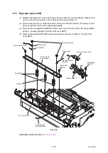
9.11 Eject jam sensor PCB
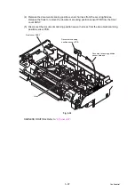
(1) Release the paper feed / eject jam sensor harness from the securing fixtures. Release the
hook to remove the eject jam sensor PCB from the sensor holder C.
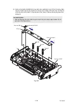
(2) Remove the two screw cup M3x6 screws, and remove the FG harness, FG spring A, and
FG spring B from the EJ pinch roller support plate.
(3) Remove the two taptite bind B M3x8 screws, and remove the EJ pinch roller support plate,
spring C, and two springs D from the front cover ASSY.
(4) Remove the taptite bind B M3x8 screw, and remove the sensor holder C from the front
cover ASSY.
Fig. 3-32
HARNESS ROUTING: Refer to
Screw cup M3x6
FG spring B
Eject jam sensor PCB
Taptite bind
B M3x8
Sensor holder C
Taptite bind
B M3x8
EJ pinch roller
support plate
FG spring A
Taptite bind B M3x8
Springs D
Spring C
Front cover ASSY
Eject jam sensor
harness
Hook
FG harness
Paper feed jam
sensor harness
Содержание ImageCenter ADS-2400N
Страница 23: ...2 4 Confidential 2 2 Paper Feeding Fig 2 2 Feed path Front side Back side ...
Страница 46: ...3 2 Confidential 2 PACKING ...
Страница 49: ...3 5 Confidential 5 LUBRICATION There are no applicable parts for lubrication ...
Страница 50: ...3 6 Confidential 6 OVERVIEW OF GEARS There are no gears to be disassembled ...
Страница 96: ...4 3 Confidential 6 Click the Machine Info The firmware version is displayed ...


