background image

CHAPTER II -17

  2.2

Paper Transfer

  2.2.1

Paper Supply

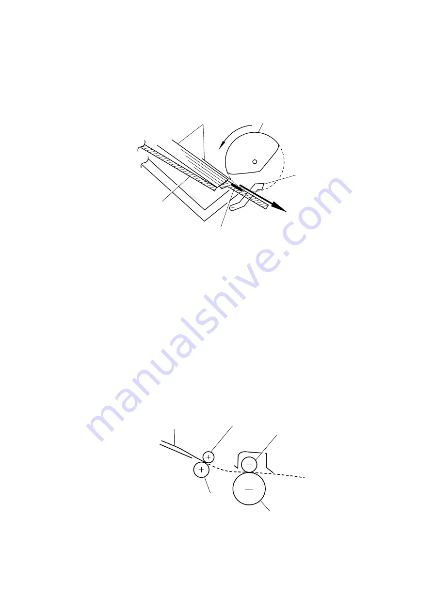
The pick-up roller picks up one sheet of paper from the paper feeder every time it is rotated
and  feeds it to the paper feed roller.

Fig. 2.19

The paper is gripped between the pick-up roller and the separation pad and separated into
individual sheets.
The pick-up roller is directly connected to the sector gear, whose rotation is forcibly
stopped by the gear stopper; when the pick-up solenoid is activated, the clutch mechanism
is engaged by the solenoid action and the sector gear is driven; when it has completed one
full turn its rotation is stopped again by the gear stopper. The paper drawn out by the
pick-up roller pushes against the top of form sensor lever and the paper top
position/absence of paper is detected by sensing the motion of the lever.

  2.2.2

Paper Registration

When paper picked up from the multi-purpose sheet feeder (MPF) pushes against the top
of form sensor actuator, the registration sensor lever is caused to turn, and the photo
sensor detects this motion. When this signal from the sensor is detected the paper feed
roller is stopped temporarily by the clutch. The paper is fed to the nip point between the
paper feed roller and the pinch roller in the multi-purpose sheet feeder, and the skew of the
paper is corrected by pushing the leading edge of the paper against the nip point. When the
paper feed roller starts to be rotated again when it is released by the clutch, paper with the
leading  edge correctly aligned, is fed by the paper feed roller and is transported to the
transfer roller.

Clutch mechanism (engaged/released by the solenoid assembly)
Released when the solenoid is ON and engaged when the solenoid is OFF.

Fig. 2.20

Hopper plate

Papers

Pick-up roller

Registration sensor lever

Separation pad

Paper

Pinch roller

Transfer roller

Drum

Paper feed roller

Содержание HL HL-1060

Страница 1: ...SERVICE MANUAL MODEL HL 1060 R LASER PRINTER ...

Страница 2: ...stered in the United States and other countries and True Type is a trademark of Apple computer Inc Epson is a registerd trademark and FX 80 and FX 850 are trademarks of Seiko Epson Corporation Hewlett Packard is a registered trademark and HP Laser Jet is a trademark of Hewlett Packard Company IBM IBM PC and Proprinter are registered trademarks of International Business Machines Corporation Microso...

Страница 3: ...ing information CHAPTER III DISASSEMBLY AND REASSEMBLY Procedures for disassembling and reassembling the mechanical system CHAPTER IV MAINTENANCE AND TROUBLESHOOTING Reference values and adjustments troubleshooting image defects troubleshooting malfunctions etc APPENDICES SERIAL NO DESCRIPTIONS CONNECTION DIAGRAMS PCB CIRCUIT DIAGRAMS Information in this manual is subject to change due to improvem...

Страница 4: ... Block Diagram II 1 1 2 Main PCB Block Diagram II 2 1 3 Main PCB II 3 1 3 1 CPU Core II 3 1 3 2 ASIC II 4 1 3 3 ROM II 7 1 3 4 Optional ROM II 7 1 3 5 DRAM II 8 1 3 6 Optional RAM II 9 1 3 7 Optional Serial I O II 10 1 3 8 EEPROM II 10 1 3 9 Reset Circuit II 11 1 3 10 Parallel I O II 11 1 3 11 Engine I O II 12 1 3 12 Paper Feed Motor Drive Circuit II 13 1 4 Driver PCB II 13 1 5 SW Panel PCB II 13 ...

Страница 5: ...EASSEMBLY III 1 1 SAFETY PRECAUTIONS III 1 2 DISASSEMBLY FLOW III 2 3 DISASSEMBLY PROCEDURE III 3 3 1 Drum Unit III 3 3 2 Output Tray ASSY III 3 3 3 Top Cover III 4 3 4 MP Sheet Feeder 1 ASSY III 4 3 5 MP Sheet Feeder 2 ASSY III 7 3 6 Under Shoot ASSY III 7 3 7 SR PCB Relay PCB III 9 3 8 Fixing Unit III 10 3 9 Scanner Unit III 14 3 10 Main PCB ASSY III 15 3 11 Base Plate ASSY III 15 3 12 Driver PC...

Страница 6: ...20 4 PAPER JAM IV 21 5 TROUBLESHOOTING MALFUNCTIONS IV 22 6 INSPECTION MODE IV 27 6 1 Incorporated Inspection Modes IV 27 6 2 Error Codes IV 29 APPENDICES 1 Serial No Descriptions V 1 2 Connection Diagram V 2 3 Main PCB Circuit Diagram 1 4 V 3 4 Main PCB Circuit Diagram 2 4 V 4 5 Main PCB Circuit Diagram 3 4 V 5 6 Main PCB Circuit Diagram 4 4 V 6 7 Driver PCB Circuit Diagram V 7 8 Switch Panel Sol...

Страница 7: ... s status using bi directional parallel communications The printer status monitor program can show the current status of your printer When printing an animated dialog box appears on your computer screen to show the current printing process If an error occurs a dialog box will appear to let you know what to correct For example when your printer is out of paper the dialog box will display Paper Empt...

Страница 8: ...ogram It can monitor the printer status while running in the background and report the current status or errors on your computer screen Popular Printer Emulation Support This printer supports three printer emulation modes HP LaserJet 5P Epson FX 850 and IBM Proprinter XL The printer also supports Auto emulation switching between HP and Epson or HP and IBM If you want to select the printer emulatio...

Страница 9: ...um unit separated from toner cartridge Life Expectancy 20 000 pages drum unit 4 coverage continuous printing at 20 pages per job 8 000 pages at 1 page per job 2 2 Functions CPU IDT 79R3041 20J 20mhz Emulation Automatic emulation selection among HP LaserJet 5P EPSON FX 850 and IBM Proprinter XL BR Script option Printer driver Windows 95 WindowsTM 3 1 driver supporting Brother Native Compression mod...

Страница 10: ...3W or less Noise Printing 49dB A or less Standing by 38dB A or less Temperature Operating 10 to 32 5 C 59 to 90 5 F Storage 0 to 40 C 38 to 104 F Humidity Operating 20 to 80 non condensing Storage 10 to 85 non condensing Dimensions W x D x H 402 W x 439 D x 274 H when the output tray is closed and the Multi purpose sheet feeder is removed Weight Approx 9 6kg 21 2lb including the drum unit and tone...

Страница 11: ...ck of paper into the feeder aligning the top edge of the sheets then push the cover back to its original position Sheet Feeder 2 Rear Paper size A4 Letter Legal B5 and Executive and other sizes of media that can be handled by the feed mechanism can be loaded except special papers such as envelopes OHP sheets labels and organizer sheets 90 to 229 mm 250 to 406mm face down Feeding direction Feedable...

Страница 12: ... paper A4 size Letter size Legal size B5 size A5 size A6 size Executive size 9 envelop size maximum printable area The recommended types of plain paper are as follows Letter Xerox 4200 75g m2 A4 Xerox 80 Premier Paper 80g m2 b Special paper specified types Labels Envelopes DL C5 COM10 Postcards Organizers K L and J sizes of DAY TIMERS Sheet Feeder 2 Rear a Normal paper 60 to 157g m2 specified type...

Страница 13: ...per Legal 100 sheets 100 sheets 157 g m 2 30 sheets 30 sheets Labels 50 sheets Special paper cut sheet Envelopes 10 sheets Postcards 30 sheets Organizers 10 sheets 2 7 Effective Printing Area Printable area A E C E B D F F The effective printing area means the area within which the printing of all the data received without any omissions can be guaranteed ...

Страница 14: ...0 24 71 dots Ç A6 105 0mm 4 13 1 240 dots 148 5mm 5 85 1 754 dots 93 0mm 3 66 1 098 dots 140 0mm 5 51 1 654 dots Ç Ç Organizer J size 69 85mm 2 75 825 dots 127 0mm 5 0 1 500 dots 57 15mm 2 25 675 dots 118 5mm 4 66 1 400 dots 6 35mm 0 25 75 dots Ç Organizer K size 95 25mm 3 75 1 125 dots 171 45mm 6 75 2 025 dots 82 55mm 3 25 975 dots 162 98mm 6 42 1 925 dots Ç Ç Organizer L size 139 7mm 5 5 1 650 d...

Страница 15: ...nly The US Food and Drug Administration FDA has implemented regulations for laser products manufactured on and after August 2 1976 Compliance is mandatory for products marketed in the United States One of the following labels on the back of the printer indicates compliance with the FDA regulations and must be attached to laser products marketed in the United States The label for Japanese manufactu...

Страница 16: ...e replace the laser unit itself To prevent direct exposure to the laser beam do not try to open the enclosure of the laser unit ACHTUNG Im Falle von Störungen der Lasereinheit muß diese ersetzt werden Das Gehäuse der Lasereinheit darf nicht geöffnet werden da sonst Laserstrahlen austreten können 1 Location of the laser beam window Fig 1 2 2 Location of Caution Label for Laser Product 200V only CLA...

Страница 17: ... O Parallel Video Control Block Interface Block Engine Control Block Operation Block Operation Panel Control System Low voltage Power Supply Block High voltage Power Supply Block Laser Scanner Unit Drive Block Stepping Motor Drum Unit Transfer Block Developing Block Drum Charging Block Cleaner Block External Device External Device Paper Tray Unit Paper Feeder Manual Feed Fixing Unit Paper Eject Bl...

Страница 18: ... RAM 2Mbytes Option RAM SIMM Max 32Mbytes Optional ROM Max 4Mbytes Option Serial I O RS232C RS422A EEPROM 512 x 8bits CPU Core R3041 A S I C Oscillator 40MHz Address Decoder DRAM Control Timer FIFO DATA EXTENSION Parallel I O Software Support EEPROM I O Engine Control I O Motor Driver To Panel Sensor PCB BUS INT To PC Fig 2 2 ...

Страница 19: ...n PCB The CPU is an IDT 79R3041 20J which is driven at a clock frequency of 20MHz This clock frequency is made by dividing the source clock frequency of 40 0MHz by two The address and data bus are both 32bits consisting of AD0 to AD31 The total addressable memory space is 4Gbytes Fig 2 3 ...

Страница 20: ... CAS WE OE and MA signals for the DRAM and controls the refresh processing CAS before RAS self refreshing method 5 Interrupt control Interrupt levels Priority High 9 TIMER 3 Watch Dog 8 MONITOR 7 FIFO 6 EXINT 5 TIMER 1 4 BD 3 SPARE 2 CDCC BOISE DATA EXTENTION Low 1 TIMER 2 Note All the interrupts can be masked 6 Timers The following timers are included Timer 1 16 bit timer Timer 2 10 bit timer Tim...

Страница 21: ...ling edge of the STROBE signal The data 8 bits from the PC is latched into the data buffer at the rising edge of the STROBE signal The pulse width of ACK varies according to the speed MODE as shown above BUSY goes LOW on the rising edge of ACK IEEE1284 support This supports the IEEE1284 data transfer with the following mode Nibble mode Byte mode ECP mode 9 Data extension This circuit extents the c...

Страница 22: ...CHAPTER II 6 12 Engine control I O This I O is used for the connection to the driver PCB It controls the main motor solenoid sensors etc Fig 2 4 ...

Страница 23: ...es of ROM The ROM is composed of two 16Mbit masked ROMs which are mounted in 42 pin IC sockets Fig 2 5 1 3 4 Optional ROM The program and the font data are stored in 4Mbytes of ROM The ROM is composed of two 16Mbit masked ROMs which are mounted in 42 pin IC sockets Fig 2 6 ...

Страница 24: ...CHAPTER II 8 1 3 5 DRAM Four 4Mbit DRAM x 8bit are used as the printer memory Fig 2 7 ...

Страница 25: ...CHAPTER II 9 1 3 6 Optional RAM A 32bit SIMM 72 pin can be fitted as optional RAM The main PCB has one slot and its capacity is for SIMM from 1Mbytes to 32Mbytes Fig 2 8 ...

Страница 26: ...I O is input to the EXINT terminal of the ASIC and recognized by the CPU A 32 byte space for a register is provided for this I O which is read and written to by the CPU Fig 2 9 1 3 8 EEPROM The EEPROM is an X24C04F two wire type with a 512 x 8bits configuration Fig 2 10 ...

Страница 27: ...1 1 3 9 Reset Circuit The reset IC is a PST591DMT The reset voltage is 4 2V typ and the LOW period of the reset signal is 50ms typ Fig 2 11 1 3 10 Parallel I O Fig 2 12 shows the parallel interface circuit Fig 2 12 ...

Страница 28: ...CHAPTER II 12 1 3 11 Engine I O Fig 2 13 shows the engine interface circuit Fig 2 13 ...

Страница 29: ...14 1 4 Driver PCB The following parts are mounted on the driver PCB Connectors Low voltage high voltage solenoid main motor toner sensor laser polygon motor connector for main PCB Registration sensor 1 5 SW Panel PCB The following parts are mounted on the SW panel PCB Operation panel 1 Key 5 LEDs ...

Страница 30: ...g regulation system to generate the regulated DC power 5V and 24V which are converted from the AC line Heater Circuit Thermal Fuse Fuse Lightning Surge Absorber Feedback Line Filter Fuse Rectifier Oscillator 24V Regulation Circuit 5V Regulation Circuit 24V 5V Lamp Heater Driver Circuit Fig 2 15 ...

Страница 31: ... Roller Supply Roller Photosensitive Drum Developing Roller Cleaner Roller Corona Unit Current Regulator Current Regulator Voltage Regulator Voltage Regulator Voltage Regulator Voltage Regulator Voltage Regulator T101 Current Regulator 24VI T1 T601 Q602 T701 Q702 Z301 PC001 PAPER SENSOR VR301 VR401 VR501 VR201 VR202 24VI GND IP001 IC PROTECTOR GND 24VI GND Fig 2 16 ...

Страница 32: ...or Tonner Fig 2 18 MP Feeder 2 cover Papers Multi purpose Sheet Feeder 1 Manual Paper Path Multi purpose Sheet Feeder 2 Papers Hopper Plate Paper Pick up Roller Pinch Roller Paper Feed Roller MP Feeder 1 Cover Paper Pick up Roller Paper Feed Roller Pitch Roller Drum Unit Blade Photosensitive Drum Transfer Roller Erase Lamp Fixing Unit Pressure Roller Eject Roller Hopper Plate Registration Sensor L...

Страница 33: ... Registration When paper picked up from the multi purpose sheet feeder MPF pushes against the top of form sensor actuator the registration sensor lever is caused to turn and the photo sensor detects this motion When this signal from the sensor is detected the paper feed roller is stopped temporarily by the clutch The paper is fed to the nip point between the paper feed roller and the pinch roller ...

Страница 34: ...oto interrupter is opened and detects the start of paper eject b When the trailing edge of the paper haspassedthrough the paper eject sensor actuator the photo sensor is closed and the completion of paper eject is recognized Fig 2 21 Fig 2 22 Transfer roller Pressure roller Drum Eject sensor actuator Eject roller Heat roller Eject sensor actuator High voltage power supply PCB Sensor Eject sensor a...

Страница 35: ...closing of the top cover Fig 2 23 2 3 2 Toner Empty Sensor Detects if there is toner in the toner cartridge It also detects whether or not the drum unit is installed The toner cartridge is installed in the drum unit Fig 2 24 Toner Empty Sensor Cover Switch Top Cover ...

Страница 36: ... 2 5 1 Charging The drum is charged to approx 1000V by an ion charge which is generated by the primary charger The charge is generated by ionization of the corona wire which has a DC bias from high voltage power supply applied to it The flow of the ion charge is controlled by the grid to ensure it is distributed evenly on the drum surface The drum sleeve is regulated to approx 280V by the voltage ...

Страница 37: ...exposed area is reduced forming the electrostatic image to be printed 1 Cycle of drum Surface Potential V 1000 700 400 300 1 2 3 4 a b Time 1 2 3 4 Primary charging Laser beam exposure and developing a Unexposed area Non image area b Exposed area Image area Transfer the image to paper Erase the residual potential Drum Sleeve Fig 2 27 Drum Paper Laser beam f lens Polygon mirror Motor Lens Laser dio...

Страница 38: ...ge area on the drum surface Fig 2 28 2 5 4 Transfer a Transfer process After the drum has been charged and exposed and has received a developed image the toner formed is transferred onto the paper by applying a negative charge to the backside of the paper The negative charge applied to the paper causes the positively charged toner to leave the drum and adhere to the paper As a result the image is ...

Страница 39: ...the cleaning stage the drum surface is exposed to the light emitted from the erase lamp LED lamp This stage prepares the drum by decreasing its surface voltage uniformly ready to receive uniform change in the primary charging stage 2 5 7 Fixing Stage An image transferred on paper by static electricity is fixed by heat and pressure when passing through the heat roller and the pressure roller in the...

Страница 40: ...anding any PCBs touch a metal portion of the equipment to discharge any static electricity charge on your body or the electronic parts or components may be damaged 6 When transporting PCBs be sure to wrap them in the correct protective packaging 7 Be sure to replace self tapping screws correctly if removed Unless otherwise specified tighten screws to the following torque values TAPTITE BIND or CUP...

Страница 41: ...CANNER UNIT PAPER SUPPORT EXTENSION SUPPORT WIRE MAIN PCB ASSY BASE PLATE ASSY DRIVER PCB LOW VOLTAGE PS PCB ASSY B B C C A A 1 3 5 7 10 11 20 UNDER SHOOT ASSY 6 OUTPUT TRAY ASSY 2 4 DRIVE UNIT MAIN MOTOR ASSY 15 GEARS and SOLENOID 16 17 18 8 9 13 FAN MOTOR 14 12 BOTTOM 19 HIGH VOLTAGE PS PCB ASSY ...

Страница 42: ...top cover 2 Lift out the drum unit Fig 3 1 3 2 Output Tray ASSY 1 Press the hinges at the left and right ends of the output tray inwards to release the output tray from the main cover Fig 3 2 Drum unit Top cover Main cover Main cover Output tray Output tray ...

Страница 43: ...ide of the main cover Fig 3 3 3 4 MP Sheet Feeder 1 ASSY Note When disassembling the MP sheet feeder ASSY the grease which smears your fingers will stick to the separation pad or the paper pick up roller and then spread to the paper and the drum unit It might cause to appear black spots on the printing page 1 Slide the upper portion of MP sheet feeder 1 toward you and remove it Fig 3 4 Main cover ...

Страница 44: ...by releasing the three hooks inside each of the covers as the following order Fig 3 6 MP feeder cover Pick up roller cover Top side cover L Tray side cover R Releasing procedure 1 Release the hook by hands 2 Release the hook by using a screwdriver 3 Release the hook by using a screwdriver 4 Pull out the tray side covers straight ...

Страница 45: ...older Then take off the spring Note If it is impossible to release the pressure plate in the above way press the side of the pressure plate while pulling the side of the sheet feeder Fig 3 8 Note Be sure to replace the regist sensor actuator film together whenever replacing the regist sensor actuator Bearing 6 Paper feed bearing Sector gear Paper pick up roller unit Separation pad Pressure plate S...

Страница 46: ...e any other parts of MP sheet feeder 2 in the same way as described for MP sheet feeder 1 Fig 3 9 3 6 Under Shoot ASSY 1 Disconnect the two cable harnesses from the relay PCB Fig 3 10 Screws MP sheet feeder 2 Screw Main cover Cable harness Relay PCB ASSY Under shoot ASSY ...

Страница 47: ...ove the two screws 3 Lift the rear portion of the under shoot assy to remove it Fig 3 11 Note Follow the number above in order when assembling Fig 3 11 1 Main cover Under shoot ASSY Plate spring Feed shaft roller ...

Страница 48: ...he relay harness ASSY connecting the SR PCB and the relay PCB and remove the two screws on the SR PCB and remove the SR PCB 4 Remove the relay PCB 5 Remove the two screws and remove the electrode SR1 SR2 Fig 3 13 SR protect sheet Taptite cup B M4x14 High voltage cover SR harness ASSY Relay harness ASSY Main cover SR PCB SR PCB Ground wire Relay PCB Taptite cup B M4x14 Taptite cup B Electrode SR2 M...

Страница 49: ...on the EL PCB Fig 3 14 3 Unhook the harness of the thermistor ASSY from the hook of the fixing unit 4 Remove the screw 5 Remove the thermistor ASSY 6 Remove the cleaner ASSY Fig 3 15 Fixing unit Cup B tight M3x14 Hook Cleaner ASSY Thermistor ASSY Fixing unit Screws Screws Thermistor connector Heater harness White Thermistor harness EL PCB ...

Страница 50: ...the boss1 of the thermistor into the hole of the fixing unit frame Do not place the thermistor on the boss2 of the fixing unit frame Fig 3 16 7 Remove the two screws 8 Open the fixing unit cover along the open side of the fixing unit cover Fig 3 17 Screws Fixing unit cover Shaft Fixing unit cover Pressure roller Thermistor Cleaner ASSY HR Boss2 Fixing unit frame Heat roller Boss1 Cleaner ASSY Fixi...

Страница 51: ... 11 Release the right side of the paper eject roller shaft 12 Remove the four eject pinch rollers and the pinch springs from the fixing unit frame Then remove the pinch spring from each pinch roller Fig 3 18a Eject Pinch Roller Paper eject roller shaft Pinch Spring Screw Cleaner ASSY HR Cleaner lock Fixing unit PR98292 ...

Страница 52: ...rame and loosen the other bind B tight 3 x 10 screw securing the fixing unit cover 15 After removing the idle gear 16 from the fixing unit frame the heat roller can be removed You can then remove the halogen heater lamp from the heat roller Note Never touch the surface of the halogen heater lamp Fig 3 20 Cleaner ASSY HR Put the cleaner ASSY HR on the heat roller and rotate it in this direction to ...

Страница 53: ... PCB 4 Remove the screw and the tape and lift the toner sensor PCB from the scanner unit Note Never touch the inside of the scanner unit or the mirror when disassembling or reassembling If there is any dirt or dust on the mirror blow it off Fig 3 22 Screws Screw Scanner unit Main cover Driver PCB Toner sensor PCB Screw Tape Scanner unit ...

Страница 54: ...e the screw to release the toner sensor harness Fig 3 22 1 3 10 Main PCB ASSY 1 Remove the four screws 2 Hold the hooks at left and right to pull out the main PCB ASSY Fig 3 23 Screw Screw Scanner unit Hook Toner sensor harness Screws Hook Main PCB ASSY ...

Страница 55: ...the printer upside down 2 Remove the five M4 and four M3 self tapping screws and one screw Fig 3 24 3 Lift the base plate ASSY and remove the grounding screw Fig 3 25 Base plate ASSY Ground wire Screw Low voltage power supply PCB ASSY Screw Taptite cup M3x2 Taptite cup M3x2 Taptite bind M4x2 Taptite cup M3x2 Base plate ASSY Soundproof sponge ...

Страница 56: ... Driver PCB ASSY 1 Remove the screw securing the driver PCB ASSY Slide the PCB A from underneath the main shield Fig 3 27 Screw Driver PCB ASSY Main shield Driver PCB ASSY The inside of the base plate Insulation tape The outside of the base plate A Dumping material Soundproof sponge A Soundproof sponge B Soundproof sponge A ...

Страница 57: ...arness Fig 3 28 Note 1 When reassembling the cable connectors must be inserted securely into the PCB connectors and the PCB must not be stressed by the harnesses Note 2 The connectors should be inserted by matching the housing color and the number of pins 3 13 Low voltage Power Supply PCB ASSY 1 Remove the screw securing the low voltage power supply PCB ASSY 2 Disconnect the two connectors for the...

Страница 58: ...eassembling the flat side of the density dial shaft must be aligned with the flat side of the density dial plastic adjustment cover 3 15 Fan Motor ASSY 1 Remove the screw securing the fan motor ASSY 2 Release the two hooks of the fan holder from the main cover Fig 3 31 Screw Density dial Main cover HV flat cable High voltage power supply PCB ASSY Screw Fan motor ASSY Hook Hook ...

Страница 59: ... 3 Remove the two screws securing the fan motor Fig 3 32 3 16 Drive Unit 1 Unhook the heater harness from the drive unit Fig 3 33 SW panel PCB Fan motor holder Fan motor Screws Heater harness Drive unit Hook ...

Страница 60: ...ft the drive unit while pressing and releasing the static removal plate spring on the drive unit Fig 3 34 3 17 Main Motor ASSY 1 Remove the four screws securing the main motor ASSY Fig 3 35 Gear cover Hook Screws Drive unit Gear cover Static removal plate spring Screws Drive unit Screws Main motor ASSY ...

Страница 61: ...III 22 3 18 Gears and Solenoid 1 Apply grease to the points shown below J J A N N N F D F N K A E G G E E E G E K A B A B D C A H M L N H C A A A H A H A A E B H F M L F Fig 3 36 ...

Страница 62: ...w Corning LTD EM 30L 5 rice grain size E Dow Corning LTD EM 30L 5 rice grain size F Dow Corning LTD EM D110 Refer to the Fig 3 36 G Dow Corning LTD EM 30L 1 rice grain size H After installing the drive unit on main body Dow Corning LTD EM 30L 5 rice grain size J After installing the drive unit on main body Kanto Kasei LTD FLOIL GE334C or GE676 1 2 rice grain size K Dow Corning LTD EM 30L 1 rice gr...

Страница 63: ...s outwards to release it Fig 3 37 3 20 Extension Support Wire 1 Raise the extension support wire toward you press both legs inward to release it and then release the paper stopper from the wire Fig 3 38 Paper support MP sheet feeder 1 2 Output tray Paper stopper Extension support wire ...

Страница 64: ...III 25 4 PACKING Fig 3 39 Documents Carton SF assy Dust cover Pad Pad PE sheet Bag Pad Pad Carton ...

Страница 65: ... occur or printed images may be blurred The print paper is damped If so use fresh paper and check whether the print quality improves or not 3 Consumables Check if The Toner lamp is not lit on the control panel when a toner cartridge is installed in the printer If the above lamp is lit replace the cartridge with a new one If blank spots occur on printouts take out the drum unit and slowly rock it t...

Страница 66: ... troubleshooting information 2 If any defective image output is found follow the image defect fault descriptions in this section 2 CONSUMABLE PARTS 2 1 Drum Unit The Drum lamp is on when the drum unit is nearly at the end of its life Life expectancy 20 000 pages at 20 pages per job 8 000 pages at 1 page per job Note There are many factors that determine the actual drum life such as temperature hum...

Страница 67: ...001 1 1 100 000 120V Fixing Unit Y Cleaner ASSY HR UH3309001 UH3310001 1 1 100 000 230V 2 Scanner Unit Y 1 100 000 3 MP sheet feeder 1 ASSY Y P pick up roller shaft ASSY Y 1 1 100 000 4 MP sheet feeder 2 ASSY Y P pick up roller shaft ASSY Y 1 1 100 000 Note The above table shows only estimated value so these values are subject to change without prior notice ...

Страница 68: ...t o u t t e s t p r i n t o u t t e s t p r i n t o u t t e s t P r i n t o u t t e s t p r i n t o P r i n t o u t t e s t p r i n t o u t t e s t p r i n t o u t t e s t P r i n t o u t t e s t p r i n t o P r i n t o u t t e s t p r i n t o P r i n t o u t t e s t p r i n t o u t t e s t p r i n t o u t t e s t P r i n t o u t t e s t p r i n t o P r i n t o u t t e s t p r i n t o u t t e s t ...

Страница 69: ...ge side 3 Is the problem solved when 4 or 5 pages are printed after the toner cartridge is replaced with a full one Yes The wiper of the toner cartridge is defective Replace the toner cartridge Drum connection failure 4 Is all the contacts HV GND connected with electrode when the drum unit is installed No Clean contact electrodes both in the printer body and on the drum unit c High voltage power s...

Страница 70: ...e wire cleaner j Corona failure contact failure 3 Are the corona electrodes between the printer body and drum unit dirty No Clean both electrodes h Drum unit failure 4 Is the problem solved when the drum unit is replaced Yes Replace the drum unit with a new one H V power supply PCB 5 Are there any disconnected connectors No Replace the H V power supply Main PCB 6 Are there any disconnected connect...

Страница 71: ...aft and the electrode c Drum unit failure 3 Is the problem solved after the drum unit is replaced Yes Replace the drum unit Scanner harness connection failure 4 Is the scanner harness connected securely Is there any play in the connection Yes Reconnect the connector properly Main Driver PCB connection failure 5 Are printing signals being input to the scanner Is the problem solved after the main PC...

Страница 72: ... on the drum h Harness connection 3 Is the scanner unit connected with the driver PCB correctly Yes Check the harness connection between the scanner unit and the driver PCB H V power supply PCB 4 Is the problem solved after H V power supply PCB replaced Yes Replace the H V power supply PCB Ditto 5 Perform the same check as in step 3 No Replace the panel sensor PCB Main PCB 6 Is the problem solved ...

Страница 73: ...r 2 2 Open the top cover 3 Turn on the power switch while holding down the switch on the control panel 4 Release the panel switch when the Drum lamp is on 5 Close the top cover 6 Hold down the panel switch until the Ready lamp is on and then release the switch 7 Print three patterns grid zip and solid black 8 Turn off the power switch with the top cover closed 9 Set paper in the manual slot with t...

Страница 74: ... in streaks Yes Replace the drum unit Scratch on the heat roller 6 Is the surface of the heat roller scratched Yes Replace the fixing unit Note Is you print the same pattern continuously the drum will be worn away and black vertical streaks appear on the paper I 7 Black and blurred horizontal stripes Possible cause Step Check Result Remedy Scratch on the drum 1 Are the horizontal stripes at 94mm O...

Страница 75: ...ched Yes Replace the drum unit I 10 Faulty registration Possible cause Step Check Result Remedy Excessive paper load 1 Is the paper loaded in the paper feeder more than 22mm deep Yes Instruct the user to keep paper loads below 22mm in depth Print paper 2 Is the specified weight of the recommended paper being used No Instruct the user to use the recommended types of paper Ditto 3 Is the first print...

Страница 76: ...or failure 3 Is the thermistor fitted correctly No Fit the thermistor correctly Low voltage power supply PCB failure 4 Is the problem solved by replacing the low voltage power supply PCB Yes Replace the low voltage power supply PCB I 12 Image distortion Possible cause Step Check Result Remedy Scanner 1 Is the scanner unit secured to the frame incorrectly Is there any play Yes Secure the unit corre...

Страница 77: ... i n t o u t t e s t p r i n t o u t t e s t p r i n t o u t t e s t P r i n t o u t t e s t p r i n t o P r i n t o u t t e s t p r i n t o u t t e s t p r i n t o u t t e s t P r i n t o u t t e s t p r i n t o P r i n t o u t t e s t p r i n t o P r i n t o u t t e s t p r i n t o u t t e s t p r i n t o u t t e s t P r i n t o u t t e s t p r i n t o P r i n t o u t t e s t p r i n t o u t t e...

Страница 78: ...unit 2 Are the spots at 63mm intervals And the problem is not solved after printing a few pages Yes Check and clean the heat roller with a cloth dampened with alcohol Replace the fixing unit SR PCB 3 Is the problem solved after the SR PCB replaced Yes Replace the SR PCB Note Clean the drum unit as follows 1 Place the printing samples in front of the process unit and find the exact portion of image...

Страница 79: ...er on the surface toner lamp comes off Fig 4 4 Caution Don t wipe the surface of the photosensitive drum with something sharp ball point pen etc Use the cleaning liquid which is mixed ethyl alcohol and pure water at the rate of each 50 Photo sensitive drum Toner cartridge Cleaning roller Paper path Separator ...

Страница 80: ...l to the most suitable position Print paper 2 Does the paper being used meet the paper specification weight etc No Recommend to change the paper to a specified type of the paper Yes Recommend to change the paper to a fresh pack paper Drum unit 3 Is the problem solved after replacing the drum unit Yes Replace the H V power supply Replace the drum unit Note The following cases raise the possibility ...

Страница 81: ...ough surface paper Yes Recommend to use the specified type of paper No Refer and compare with I 14 I 19 Downward fogging of solid black Possible cause Step Check Result Remedy Drum unit 1 Is the problem solved after replacing the drum unit Yes Replace the drum unit SR PCB 2 Is the problem solved after replacing the SR PCB Yes Replace the SR PCB ...

Страница 82: ... failure 1 Is the problem solved after replacing the drum unit which contains no more starter sheet Yes Replace the drum unit SR PCB failure 2 Is the problem solved after replacing the SR PCB Yes Replace the SR PCB High voltage power supply PCB failure 3 Is the problem solved after replacing the High voltage power supply PCB Yes Replace the High voltage power supply PCB Note Make sure to use the u...

Страница 83: ...For transfer roller Drum unit fFor cleaning roller gFor grid jWire cleaner hFor corona wire iFor development roller kFor supply roller To SR PCB For supply roller Grounding wire For drum For development roller For corona wire For cleaning roller For transfer roller For corona wire For drum For transfer roller For cleaning roller For grid For development roller ...

Страница 84: ...CHAPTER IV 20 3 4 Location of Feed Roller Shaft and Grounding Contacts Fig 4 7 Feed shaft roller For feed roller ...

Страница 85: ... of the problem Paper was fed approx 20mm transfer roller Jam caused by delay of paper feed Due to the paper dust or rubber of the paper feed roller war paper was not fed in proper timing Remove the paper dust attached to the paper feed roller If the rubber is worn out replace it with new one Top of paper stopped at 17mm from the contact point of the heat roller and pressure roller Jam caused pape...

Страница 86: ...power plug Yes Replace the AC power cord M 2 No DC power supplied Possible cause Step Check Result Remedy AC power supply 1 Is AC power supplied between connectors CN1 L and CN1 N when the power plug is plugged into the outlet No Follow the same check procedure of M 1 No AC power supplied Wiring DC load 2 Turn the power switch OFF and disconnect the P13 connector Driver PCB Turn the power switch O...

Страница 87: ...ssible cause Step Check Result Remedy Connection failure 1 Is the contact of connector P11 on the driver PCB good No Reconnect the connector Driver PCB circuit 2 Set paper on the manual paper slot and make the test print by pressing the switch on the control panel No Replace the driver PCB Paper pick up clutch solenoid Does the voltage between pins 2 SOLENOID and 1 24V of the P11 connector on the ...

Страница 88: ...tact burns Yes Clean the SR bias contact Ditto 2 Check the connection of the harness between the SR PCB and the driver PCB Yes Replace the SR PCB M 7 Fixing heater temperature failure Possible cause Step Check Result Remedy Poor thermistor harness contact 1 Are the connectors on the erase lamp PCB and the high voltage power supply PCB secured correctly No Connect the connectors securely Blown ther...

Страница 89: ...ction failure 1 Is the connection of the scanner motor connector P2 on the driver PCB secured No Reconnect the connectors securely Power supply input 2 Is the voltage between pins 1 24VDC and 2 GND of connector P2 on the driver PCB 24 Volts DC No Check if 24VDC is supplied between pins 4 5 24VDC and 2 3 24VRET of connector P13 on the driver PCB If not check the power supply output on the low volta...

Страница 90: ... 2 Wrinkles Possible cause Step Check Result Remedy Paper 1 Is paper of a recommended type being used No Instruct the user to use the recommended types of paper 2 Is the wrinkle problem solved if new paper is used Yes Instruct the user how to store paper so that it does not absorb moisture Fixing unit entrance guide 3 Is the entrance guide dirty Yes Clean the entrance guide Fixing unit 4 Is the pr...

Страница 91: ...s turn ON in the order Drum Alarm Ready Data Drum When you release the switch a mode is selected The mode selected is indicated by the lamp which is ON when you release the switch The inspection modes are assigned to the respective lamps as shown below Lamp Type of inspection Drum Factory inspection mode Alarm Continuous grid pattern print mode Ready 3 patterns print mode grid Æzip Æblack Data NV ...

Страница 92: ... OFF open the top cover and remove the drum unit 2 Turn the printer power switch ON while holding down the control panel switch The Drum lamp comes ON 3 Lightly press the panel switch again 4 Check that the Drum paper eject sensor and Alarm registration sensor lamps go OFF after all the lamps have been ON If the paper eject sensor is ON at this point the Drum lamp stays ON error If the registratio...

Страница 93: ...r Fuser Malfunction Laser BD Malfunction Scanner Malfunction ROM Error D RAM Error Service A Service B NV RAM Error CPU Runtime Error Main Motor Error Refer to the further description of those errors as follows Service A Address Error Service B Buse Error CPU Runtime Error The error which CPU other than the above two detects such as Illegal Instruction or Operation Overflow HOW THE LED INDICATE AN...

Страница 94: ... the process unit Drum unit with toner cartridge 6 D 3 0 0 0 0 A N B 3 Drum unit on the drum unit 6 E B 0 0 0 0 0 1 4 Toner cartridge on the toner cartridge 6 3 3 1 0 2 8 E 0 5 N B 0 5 Scanner unit on the scanner unit 1 9 0 0 1 MONTH YEAR FACTORY ID NO SERIAL NO YEAR MONTH DATE SERIAL NO LINE NO TONER TYPE YEAR MONTH ASSEMBLY SERIAL NO SERIAL NO DATE MONTH X OCT Y NOV Z DEC YEAR FILLING AMOUNT 0 1...

Страница 95: ...1 S W 1 P 1 S W P A N E L P C B F A N L A S E R P 2 S C A N M O T O R S C A N N E R M O T O R P 3 T O N E R P 1 E R A S E L A M P T R T R A N S F E R P C B C H G D R B H V P S P 9 E L P 1 P 1 P 2 P 2 P 3 R E L A Y P C B R E S I S T S O L E N O I D 2 B I N S O L E N O I D 1 B I N S O L E N O I D M D C M O T O R P 1 3 L O W V O L T A G E P 1 1 S O L R E S I P 1 2 D C M O T O R D R I V E R P C B C N ...

Страница 96: ...Appendix 3 Main PCB Circuit Diagram 1 4 CODE UK3400000 B48K246CIR NAME V 3 ...

Страница 97: ...Appendix 4 Main PCB Circuit Diagram 2 4 CODE UK3400000 B48K246CIR NAME V 4 ...

Страница 98: ...Appendix 5 Main PCB Circuit Diagram 3 4 CODE UK3400000 B48K246CIR NAME V 5 ...

Страница 99: ...Appendix 6 Main PCB Circuit Diagram 4 4 CODE UK3400000 B48K246CIR NAME V 6 ...

Страница 100: ...Appendix 7 Driver PCB Circuit Diagram CODE UK3634000 B48K280CIR NAME V 7 ...

Страница 101: ...Appendix 8 Switch Panel Solenoid Bin Relay PCB Circuit Diagram CODE UK3635000 281 282 283 CIR NAME V 8 ...

Страница 102: ...R22 TRA1 R20 R21 CN2 R101 D110 Q101 R106 PC1 R104 R105 VR101 R103 C110 R102 Q2 Q1 R19 R13 R11 C9 R8 D5 C10 C12 R12 PC1 R6 R14 R10 C11 D7 R7 D4 D6 R17 D2 R4 C6 C7 C15 FG V 9 D104 VR301 R304 R302 R301 R305 R113 C101 C303 C306 IC301 Q301 D302 T201 BEA301 R208 R202 R201 Q201 D101 C109 Q202 R303 C301 R204 C202 FG R205 R201 R203 C203 R204 R206 D201 C302 R114 PC2 R110 C C A B 24V GND 5V REM CN101 A ...

Страница 103: ...R22 TRA1 R20 R21 CN2 R101 D110 Q101 R106 PC1 R104 R105 VR101 R103 C110 R102 Q2 Q1 R19 R13 R11 C9 R8 D5 C10 C12 R12 PC1 R6 R14 R10 C11 D7 R7 D4 D6 R17 D2 R4 C6 C7 C15 FG R3 V 10 D104 VR301 R304 R302 R301 R305 R113 C101 C303 C306 IC301 Q301 D302 T201 BEA301 R208 R202 R201 Q201 D101 C109 Q202 R303 C301 R204 C202 FG R205 R201 R203 C203 R204 R206 D201 C302 R114 PC2 R110 C C A B 24V GND 5V REM CN101 A ...

Страница 104: ... R505 D502 C501 R503 R506 R301 R401 R402 C301 C402 C401 ZD401 Q301 Q401 Q502 Q501 VR501 VR301 VR401 C204 C502 R208 Q202 Q203 C103 R601 R602 R605 R701 R702 R703 R704 R705 ZD701 Q701 C702 C709 C708 C707 D704 C710 Q702 Q703 D703 R717 R715 R714 R713 R718 C701 D702 R706 R716 C602 C603 R604 R610 R607 R608 R611 D605 Q602 0101 D101 D603 D604 D606 Q601 R609 ZD601 Q204 C203 R103 ZD101 R108 R107 R110 R101 R2...

Страница 105: ...Appendix 12 SR PCB Circuit Diagram CODE UK3653000 B48K284CIR NAME V 12 ...

Отзывы: