

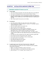


CHAPTER 2 INSTALLATION AND BASIC OPERATION
2-6
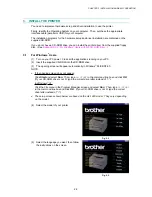
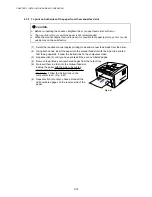
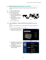
(4) Extend the tray extension flap. After the
printer has warmed up the Ready LED
changes from blinking to lit. (Fig. 2-12)
(5) Press the control panel button. The
printer will print a test page. Check the
test page printed correctly.
Fig. 2-12
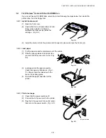
3.2.4
Connect the printer and the computer
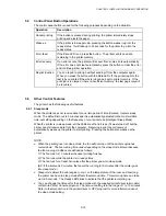
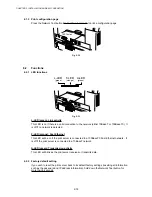
(1) Turn off the power switch.
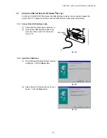
(2) Connect the parallel interface to the
computer, then connect it to the printer.
(Fig. 2-13)
(3) Use the clips on the printer connector to
secure the parallel interface cable.
(4) Turn on the printer power switch.
Fig. 2-13
3.2.5
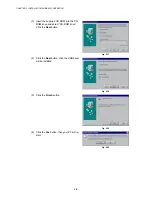
Install the printer driver from floppy disk
(1) Turn on the computer power. If the “Add New Hardware Wizard” window appears, click
the Cancel button.
(2) Insert the supplied floppy disk into the floppy disk drive.
(3) Install the printer driver using the Setup.exe file.
In Windows
95/98
i) Click
the
Start button and select Run.
ii) Type
A:\SETUP
and click OK. (If your floppy disk drive is not A, insert the correct drive
letter instead of ‘A’.)
iii) Follow the instructions that appear on the screen.
In Windows
3.1
i)
Click File menu in the Program Manager screen and select Run.
ii) Type
A:\SETUP
click OK. (If your floppy disk drive is not A, insert the correct drive letter
instead of ‘A’.)
iii) Follow the instructions that appear on the screen.
Parallel interface
cable
Содержание HL-1030
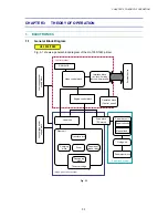
Страница 51: ...CHAPTER 3 THEORY OF OPERATION 3 9 Fig 3 8 ...
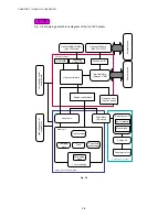
Страница 53: ...CHAPTER 3 THEORY OF OPERATION 3 11 Two 32 Mbits ROMs x 16 bit are fitted Fig 3 11 HL 1270N ...
Страница 55: ...CHAPTER 3 THEORY OF OPERATION 3 13 Two 16M bit DRAMs x 16 bits are used as the RAM Fig 3 14 HL 1250 1270N ...
Страница 122: ...CHAPTER 5 PERIODIC MAINTENANCE 5 8 ...
Страница 198: ...CODE UK4352000 B512040CIR 1 2 A 20 NAME Appendix 11 Main PCB Circuit Diagram HL 1030 1240 1 2 ...
Страница 199: ...Appendix 12 Main PCB Circuit Diagram HL 1030 1240 2 2 CODE UK4352000 B512040CIR 2 2 A 21 NAME ...
Страница 200: ...Appendix 13 Main PCB Circuit Diagram HL 1250 1270N 1 5 CODE UK4361000 B512049CIR 1 5 A 22 NAME ...
Страница 201: ...Appendix 14 Main PCB Circuit Diagram HL 1250 1270N 2 5 CODE UK4361000 B512049CIR 2 5 A 23 NAME ...
Страница 202: ...CODE UK4361000 B512049CIR A 24 NAME Appendix 15 Main PCB Circuit Diagram HL 1250 1270N 3 5 ...
Страница 203: ...CODE UK4361000 B512049CIR 4 5 A 25 NAME Appendix 16 Main PCB Circuit Diagram HL 1250 1270N 4 5 ...
Страница 204: ...CODE UK4361000 B512049CIR 5 5 A 26 NAME Appendix 17 Main PCB Circuit Diagram HL 1250 1270N 5 5 ...
Страница 205: ...Appendix 18A Engine PCB Circuit Diagram OLD CODE UK4444000 B512059CIR A 27 NAME ...
Страница 206: ...Appendix 18B Engine PCB Circuit Diagram NEW CODE UK4444000 B512059CIR A 28 NAME ...
Страница 207: ...Appendix 19 Network Board Circuit Diagram HL 1270N CODE LJ8107000 B512058CIR A 29 NAME ...
Страница 218: ...INDEX vi ...


