CHAPTER 4 DISASSEMBLY AND RE-ASSEMBLY
4-31
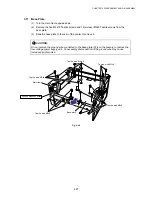
3.15
Engine PCB ASSY / High-Voltage Power Supply PCB ASSY
(1) Remove the M4x12 Taptite screw to remove the insulation sheet.
(2) Remove the three M4x12 Taptite screws securing the engine PCB and the high-voltage
power supply PCB.
(3) Lift the engine PCB and high-voltage power supply PCB together and disconnect the
connector which connects two PCBs together to remove the high-voltage power supply
PCB ASSY.
(4) If necessary, remove the T/R electrode helical spring from the T/R plate.
Fig. 4-55
!
CAUTION:
Be sure not to lose the T/R electrode helical spring after removing it.
NOTE:
When re-assembling the T/R electrode helical spring onto the plate, press the spring onto the
plate firmly with a flat bladed screwdriver and ensure that it is retained securely.
!
CAUTION:
The high-voltage power supply PCB has been upgraded from the middle of September
’99 production to improve the print quality.
In accordance with the change the T/R electrode helical spring has been also changed.
As we supply both old and new versions of high-voltage power supply PCB and helical
spring, ensure that you replace the same version of them.
The old and new versions are incompatible each other. For details, refer to the parts
reference list.
Screw, bind M4x12
Screw, bind M4x12
Engine PCB ASSY
High-voltage power
supply PCB ASSY
T/R electrode
helical spring
Chute
Insulation sheet
Screw, bind M4x10
Step (4)
Step (3)
Содержание HL-1030
Страница 51: ...CHAPTER 3 THEORY OF OPERATION 3 9 Fig 3 8 ...
Страница 53: ...CHAPTER 3 THEORY OF OPERATION 3 11 Two 32 Mbits ROMs x 16 bit are fitted Fig 3 11 HL 1270N ...
Страница 55: ...CHAPTER 3 THEORY OF OPERATION 3 13 Two 16M bit DRAMs x 16 bits are used as the RAM Fig 3 14 HL 1250 1270N ...
Страница 122: ...CHAPTER 5 PERIODIC MAINTENANCE 5 8 ...
Страница 198: ...CODE UK4352000 B512040CIR 1 2 A 20 NAME Appendix 11 Main PCB Circuit Diagram HL 1030 1240 1 2 ...
Страница 199: ...Appendix 12 Main PCB Circuit Diagram HL 1030 1240 2 2 CODE UK4352000 B512040CIR 2 2 A 21 NAME ...
Страница 200: ...Appendix 13 Main PCB Circuit Diagram HL 1250 1270N 1 5 CODE UK4361000 B512049CIR 1 5 A 22 NAME ...
Страница 201: ...Appendix 14 Main PCB Circuit Diagram HL 1250 1270N 2 5 CODE UK4361000 B512049CIR 2 5 A 23 NAME ...
Страница 202: ...CODE UK4361000 B512049CIR A 24 NAME Appendix 15 Main PCB Circuit Diagram HL 1250 1270N 3 5 ...
Страница 203: ...CODE UK4361000 B512049CIR 4 5 A 25 NAME Appendix 16 Main PCB Circuit Diagram HL 1250 1270N 4 5 ...
Страница 204: ...CODE UK4361000 B512049CIR 5 5 A 26 NAME Appendix 17 Main PCB Circuit Diagram HL 1250 1270N 5 5 ...
Страница 205: ...Appendix 18A Engine PCB Circuit Diagram OLD CODE UK4444000 B512059CIR A 27 NAME ...
Страница 206: ...Appendix 18B Engine PCB Circuit Diagram NEW CODE UK4444000 B512059CIR A 28 NAME ...
Страница 207: ...Appendix 19 Network Board Circuit Diagram HL 1270N CODE LJ8107000 B512058CIR A 29 NAME ...
Страница 218: ...INDEX vi ...


