CHAPTER 6 TROUBLESHOOTING
6-42
8. INCORRECT
PRINTOUT
When the data is not printed correctly as it is seen on the PC screen, follow the procedures
below in the event of a specific error.
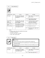
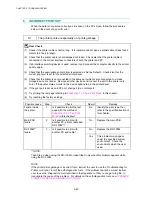
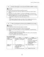
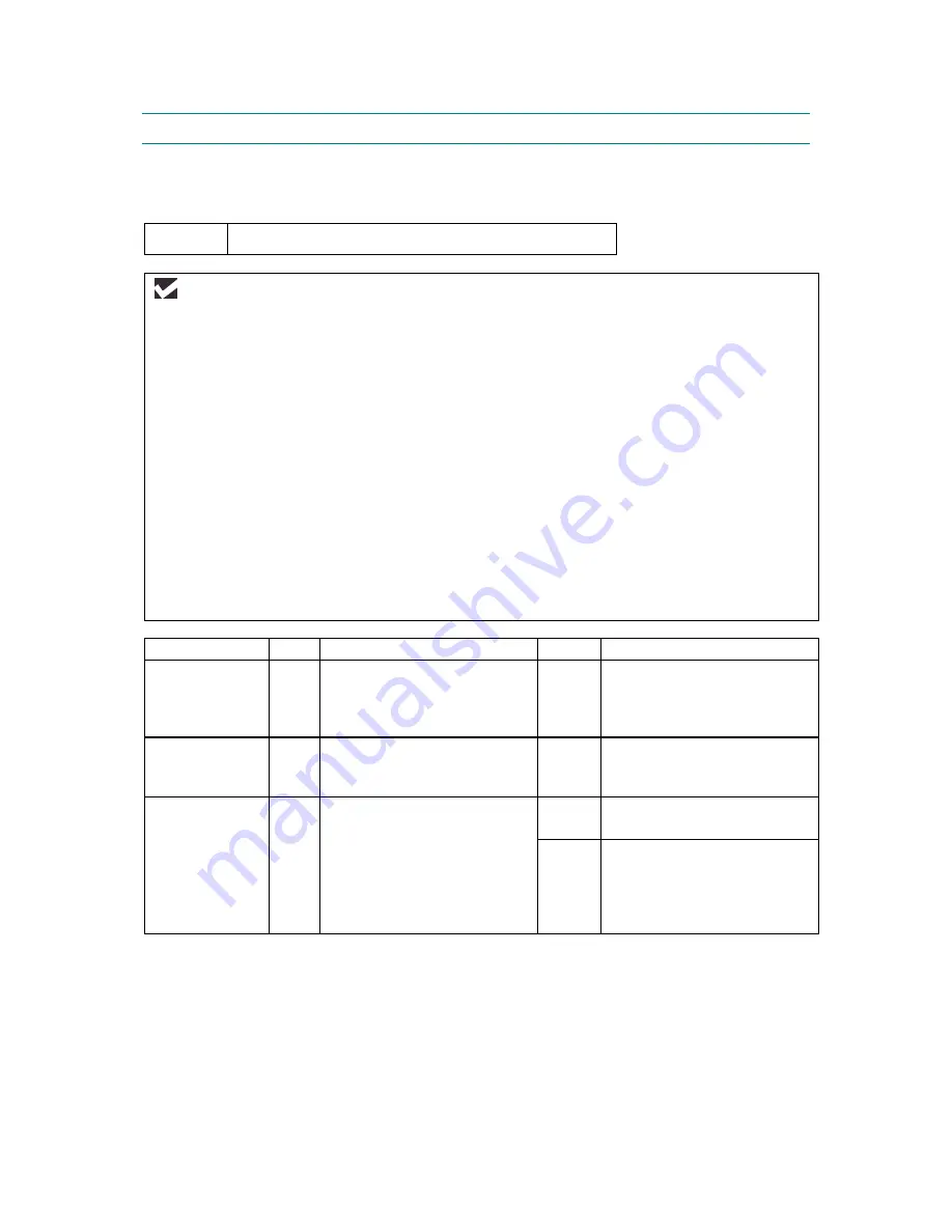
P-1
The printer prints unexpectedly or it prints garbage.
User Check
(1) Check if the printer cable is not too long. It is recommended to use a parallel cable of less than 2
meters (6.6 feet) in length.
(2) Check that the printer cable is not damaged or broken. Check also that the printer cable is
connected to the correct interface connectors of both the printer and PC.
(3) If an interface switching device is used, remove it and connect the computer directly to the printer
and try again.
(4) Check that the appropriate printer driver is selected as ‘Set as Default’. Check also that the
correct print port is set for the selected printer driver.
(5) Check that the printer is not connected to the same port which is also connected to a mass
storage device or scanner. Remove all other devices and connect the port to the printer only.
Turn off the printer status monitor in the device options tab in the printer driver.
(6) If the print port is set as an ECP port, change it to a normal port.
(7) Try printing the test page referring to
Subsection 10.1 ‘Test Print Mode’
in this chapter.
(8) Try resetting the factory settings.
Possible cause
Step
Check
Result
Remedy
Failure inside
the printer
1
Is it possible to print the test
page with the method of
Subsection 10.1 ‘Test Print
Mode’
in this chapter?
No
Identify the error type, then
refer to the specified section of
this chapter.
Main PCB
failure
2
Is it possible to print with
another PC, printer cable and
RS-100M**?
No
Replace the main PCB.
RS-100M**
failure
3
Is it possible to print with
another PC and cable?
No
Replace the RS-100M.
Yes
This problem may appear
under the specified system
environment. Check the
environment which the user
used.
**NOTE:
Take Step 2 when using the RS-100M or take Step 3 only when this problem appears while
using the RS-100M.
NOTE:
If the printer prints garbage or incorrect fonts, instruct the user to use the ‘Troubleshooting for
Printer won’t print’ tool of the self-diagnostics tools. If the problem cannot be solved, instruct
user to use the ‘Diagnostics’ tool described in the Appendix so that you can get a log file to
investigate the cause of the problem. For details on the self-diagnostics tools, see
APPENDIX
5 ‘HOW TO USE SELF-DIAGNOSTICS TOOLS’
.
Содержание HL-1030
Страница 51: ...CHAPTER 3 THEORY OF OPERATION 3 9 Fig 3 8 ...
Страница 53: ...CHAPTER 3 THEORY OF OPERATION 3 11 Two 32 Mbits ROMs x 16 bit are fitted Fig 3 11 HL 1270N ...
Страница 55: ...CHAPTER 3 THEORY OF OPERATION 3 13 Two 16M bit DRAMs x 16 bits are used as the RAM Fig 3 14 HL 1250 1270N ...
Страница 122: ...CHAPTER 5 PERIODIC MAINTENANCE 5 8 ...
Страница 198: ...CODE UK4352000 B512040CIR 1 2 A 20 NAME Appendix 11 Main PCB Circuit Diagram HL 1030 1240 1 2 ...
Страница 199: ...Appendix 12 Main PCB Circuit Diagram HL 1030 1240 2 2 CODE UK4352000 B512040CIR 2 2 A 21 NAME ...
Страница 200: ...Appendix 13 Main PCB Circuit Diagram HL 1250 1270N 1 5 CODE UK4361000 B512049CIR 1 5 A 22 NAME ...
Страница 201: ...Appendix 14 Main PCB Circuit Diagram HL 1250 1270N 2 5 CODE UK4361000 B512049CIR 2 5 A 23 NAME ...
Страница 202: ...CODE UK4361000 B512049CIR A 24 NAME Appendix 15 Main PCB Circuit Diagram HL 1250 1270N 3 5 ...
Страница 203: ...CODE UK4361000 B512049CIR 4 5 A 25 NAME Appendix 16 Main PCB Circuit Diagram HL 1250 1270N 4 5 ...
Страница 204: ...CODE UK4361000 B512049CIR 5 5 A 26 NAME Appendix 17 Main PCB Circuit Diagram HL 1250 1270N 5 5 ...
Страница 205: ...Appendix 18A Engine PCB Circuit Diagram OLD CODE UK4444000 B512059CIR A 27 NAME ...
Страница 206: ...Appendix 18B Engine PCB Circuit Diagram NEW CODE UK4444000 B512059CIR A 28 NAME ...
Страница 207: ...Appendix 19 Network Board Circuit Diagram HL 1270N CODE LJ8107000 B512058CIR A 29 NAME ...
Страница 218: ...INDEX vi ...


